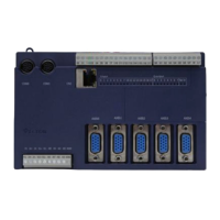
TCI-W11, TCI-W22 Universal Controller
OUTPUT CONFIGURATION
Doc: 70-00-0158C, V2.0-20220523 © Vector Controls GmbH, Switzerland Page 16-22
Subject to alteration
Digital output configuration (1d, 2d)
Settings for digital outputs (1d00 / 2d00 = OFF, 1d05 / 2d05 = 0), 1d =DO1, 2d = DO2
Enable digital/PWM or floating point (3-point valve) output
OFF= DO1 and DO2 are two digital/PWM outputs
ON = DO1 and DO2 are one floating point output (DO1 open, DO2 close)
Select control loop or special function (0= OFF)
1= LP1, 2= LP2
3= Dehumidify (4 pipe, max LP1 cooling, LP2 direct)
4= Manual positioning (on/off)
5= State functions
When 1d01 = 1, configure output:
0= Stage 1 heating/reverse
1= Stage 1 cooling/direct
2= Stage 1 heating and cooling, reverse and direct
3= Stage 2 heating/reverse
4= Stage 2 cooling/direct
5= Stage 2 heating and cooling, reverse and direct
If 1d01 = 4 Manual positioning or time schedule controlled
0= Time schedule controlled only
1= Manual positioning and time schedule controlled
When 1d01 = 5, select state functions:
0= ON if controller operation state is ON
1= ON while demand on any output
2= ON while controller in heating mode and operation state ON
3= ON while controller in cooling mode and operation state ON
Switch-off delay (time output active with no more demand)
Delay is in seconds or minutes depending on d09
Switch-on delay(time demand active before output on)
In state mode 1d01=5 outputs disabled during switch-on delay
Delay is in seconds or minutes depending on d09
Activate PWM, set cycle time, seconds (>0 activates, 0 deactivates)
Choose alarm to set output to ON (output OFF on conflicting alarms)
Alarm: 1 2 3 4 5 6 7 8
Choose alarm to set output to OFF (output OFF on conflicting alarms)
Alarm: 1 2 3 4 5 6 7 8
Display fan symbol while active
Binary switching delays in minutes or seconds
OFF = delays are in seconds, ON = delays are in minutes
➔ Low and high limit alarms are defined with input parameters. With output parameters assign
an alarm to an output and select output state. Each alarm’s required output can be
individually selected. Multiple alarms can be signed to one output. Should one alarm be
simultaneously selected to activate and deactivate the output, the one to de-activate has
precedence.
➔ With manual positioning (1d01=4) position the output directly (ON/OFF).
➔ With dehumidifying (1d01=3) the maximum value is taken of cooling and dehumidifying. When the humidity is too
high, cooling will continue to operate, even without a demand for cooling, to dehumidify the air and heating will
activate to maintain comfort.
➔ State functions (1d01=5) activate the output based on certain conditions with or without a demand for heating or
cooling, in either occupied (comfort) or unoccupied (standby) mode. In Energy Hold OFF mode (EHO) the output will
be off.
Output Priority
1. Alarm level low
2. Alarm level high
3. Operation mode OFF
4. Control function
 Loading...
