Legend
T, U Input signal temp/universal
X
PH
P-band heating/direct
X
PC
P-band cooling/reverse
X
DZ
Dead zone h/c set points
X
SBY
Economy mode set point shift
W
H
Set point heating/reverse
W
C
Set point cooling/direct
Y
H1,
Y
R1
PI sequence heating/reverse
Y
C1,
Y
D1
PI sequence cooling/direct
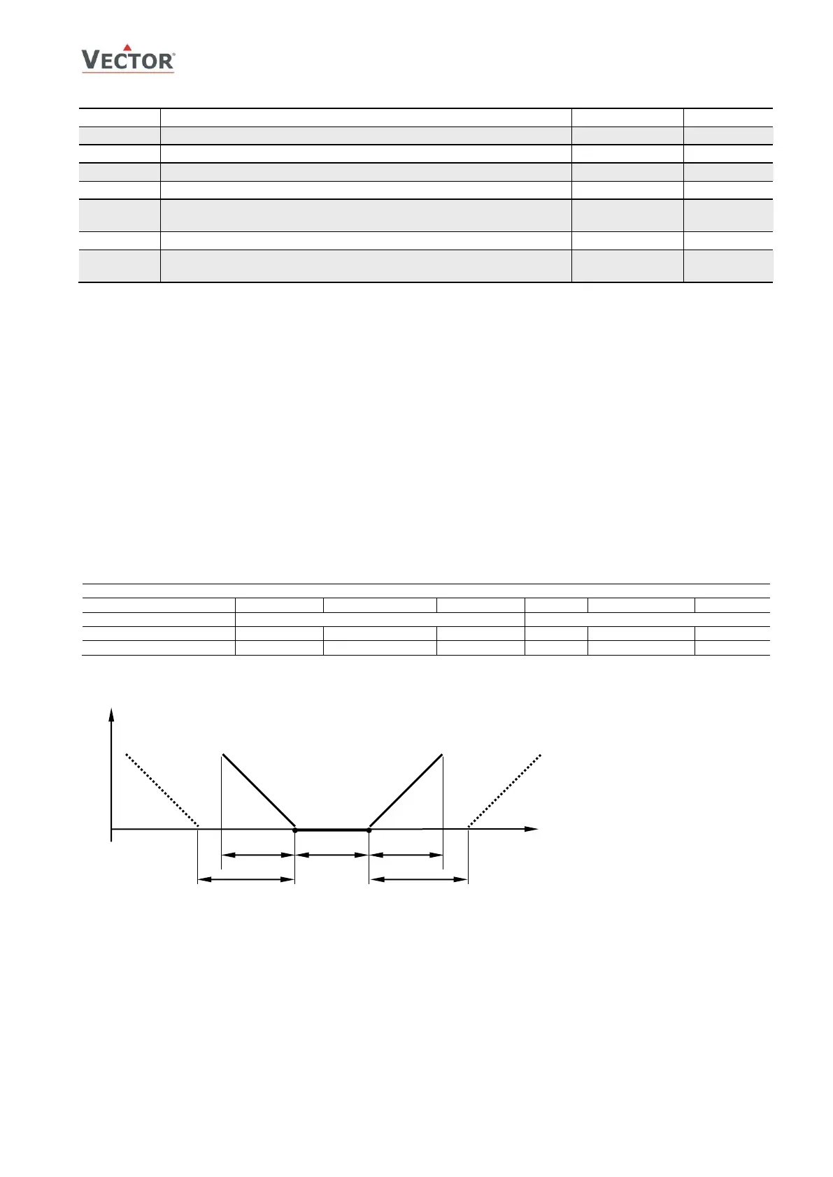
➔ Proportional control(P-band)
The proportional control function calculates the output based on the difference between setpoint and measured value.
The proportional band (P-band) defines the difference between setpoint and measured value which will result in a 100%
output. For example, with a heating or reverse 0-10v control sequence, and a 2.0°C (4.0°F) P-band value, at 10v the
controller will be 2.0°C (4.0°F) below setpoint. This is the working range of the proportional control sequence.
Setting the proportional band to 0 disables proportional control.
➔ Integral and Differential control
Proportional control is in most cases a very stable control mode. The flaw of proportional control alone, however, is
that the setpoint is normally not reached. As the measured value gets closer to the setpoint, the output reduces until
it reaches a point, a fraction above or below the setpoint, where the output equals the load. To reach the setpoint and
achieve a higher level in comfort the Integral/Differential function should be activated.
Integral Gain (KI)dynamically increases the output by the selected KI value every Measuring Interval TI until the
setpoint is reached. The challenge is to prevent hunting, where the output increases too fast, the temperature
overshoots the setpoint, the output goes to 0, the temperature undershoots the setpoint, and the cycle repeats itself.
Hunting may result if the integral gain is too high or measuring interval too short. Each system is different. To
prevent instability the P-band should be extended when integral gain is active (L14 or L15 set above 0).
Setting the integral gain to 0 disables integral and differential control.
 Loading...