Doc: 70-00-0140C, V2.0-20220523 © Vector Controls LLC, USA Page 16-24
Subject to alteration
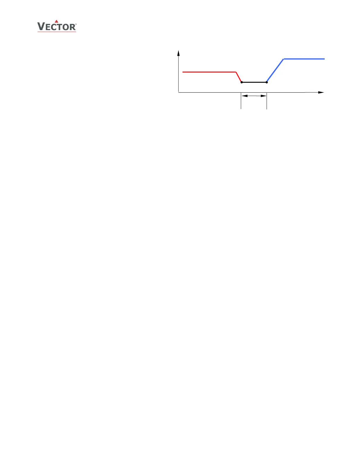
➔ For VAV Function individual minimum and
maximum limits may be assigned for cooling and
heating. In VAV applications maximum cooling
output matches the maximum air volume the
VAV box is set to deliver. As demand for airflow
in cooling mode decreases, airflow dwindles until
it reaches minimum cooling output (1A05). This
minimum will be based on the airflow needed at
design cooling and is typically 10% to 15% of
maximum cooling airflow. When this minimum is
reached the system is in dead-band – neither
heating nor cooling. Minimum airflow in heating
mode is set with 1A03. As the system moves into
heating mode, heating airflow increases until it reaches the maximum heating output (1A04), typically 30 to 50% of
maximum cooling airflow.
 Loading...


