VEC-1290K Instruction Manual AM Radio Transmitter
leads should be formed as shown below. Install and solder resistors at the
followin
locations:
Important Note: the fourth resistor color band is for tolerance, and is not called
out in the followin
ste
s.
1. Find the 15-ohm (brown-green-black) '/,watt resistor.
2. Install the 15-ohm resistor at R2 on the printed circuit board.
3. Solder and trim the leads.
4. Find the 1K-ohm (brown-black-red)
1
/4-watt
resistor. 5. Install and solder at R3.
6. Find the 4.7K-ohm (yellow-violet-red) '/.-watt
resistor. 7. Install and solder at R4.
9. Check each solder joint. Look for solder splashes, bridges (a bridge is
where solder has made a connection between two or more points
that should not be connected
, or
oor solder connections.
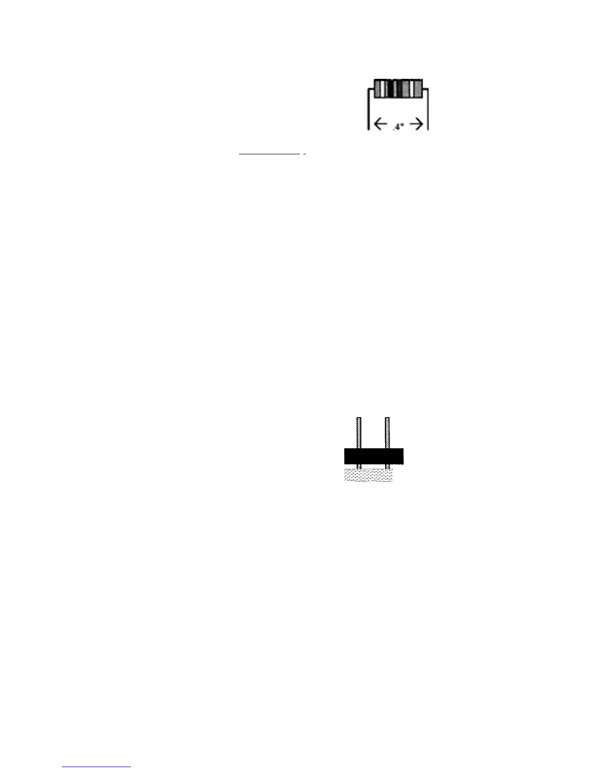
Phase 2: Jum
er Headers
[ ] [ ] 1. Locate the five 2-
in
um
er headers.
Short pins into
pc
O O board holes
 Loading...