VEC-I290K Instruction Manual AM Radio Transmitter
Phase 4: Molded choke installation
Important Note: only the first three color bands are specified in the following
directions. The fourth band is for tolerance and ma
be disre
arded.
1. Locate the 1000-uH molded choke (brown-black-red). Install and
solder at location L1.
2. Locate the 22-uH molded choke (red-red-black). Install and solder at
location L2.
3. Locate the 680-uH molded choke (blue-gray-brown). Install and solder
at location L3.
4. Locate the two 330-uH (orange-orange-brown) molded chokes. Install
and solder at locations:
5. L4 330 uH
oran
e-oran
e-brown
.
6. L9 330 uH
oran
e-oran
e-brown
.
7. Locate the two 180-uH (brown-gray-brown) molded chokes. Install and
solder at the following locations:
8. L5 180 uH (brown-gray-brown).
9. L6 180 uH (brown-gray-brown).
and solder at the followin
11. L7 100 uH
brown-black-brown
.
12. L8 100 uH
brown-black-brown
.
rnase 5: IC Sockets/ICs
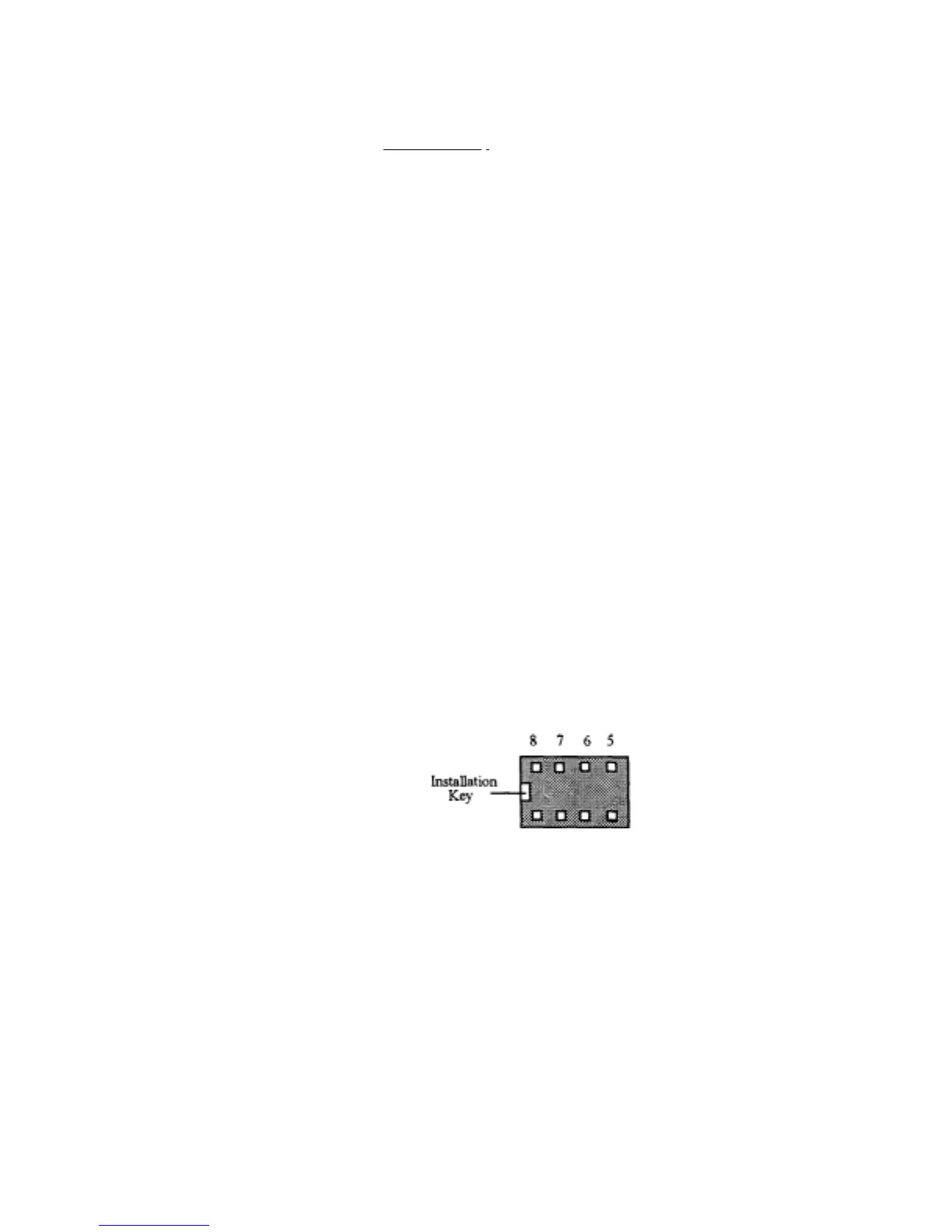
1. Locate the 8-pin DIP IC socket. Note that the socket is "keyed", and
should be installed with its key aligned to the silk-screened outline
on the PC board.
1 2 3 4 Pin
To
view o
 Loading...