Do you have a question about the Veichi AC300 Series and is the answer not in the manual?
Essential safety guidelines and warnings for operating the inverter.
Instructions and checks to perform before operating the inverter.
Specifications and performance criteria for the inverter.
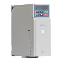
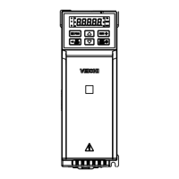
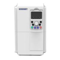
Physical dimensions and mounting specifications for the plastic inverter model.
Physical dimensions and mounting specifications for the steel inverter model.
Visual layout and components of the inverter's control keyboard.
Detailed explanation of each key's function and operation.
Meaning and state of the indicator lights on the inverter.
Core operational parameters for the inverter's basic functions.
Parameters related to the operational control of the inverter.
Settings and configurations for analog input/output terminals.
Parameters related to the overall system configuration and settings.
Parameters specific to the connected motor's characteristics.
Parameters for Vector Control (VC) mode motor operation.
Parameters for controlling motor torque and related settings.
Parameters for Voltage/Frequency (V/F) control of the motor.
Parameters for inverter protection and malfunction handling.
Parameters for configuring the PID process control loop.
Parameters for multi-speed operation and PLC functions.
Parameters for communication control via Modbus and other protocols.
Configuration of input and output terminal functions.
Codes and values for monitoring inverter states and parameters.
Monitor group for diagnosing malfunctions and their states.
List and descriptions of fault codes and their types.
Guidelines for periodic inspection and maintenance of the inverter.
Procedures for regular maintenance to ensure optimal performance.
Format and structure of Modbus communication data frames.
Address mapping for Modbus communication control parameters.
| Protection Level | IP20 |
|---|---|
| Cooling Method | Forced air cooling |
| Output Voltage | 0~Rated Input Voltage |
| Control Mode | V/F control |
| Power Range | 0.4kW |
| Overload Capacity | 150% for 60 seconds |
| Braking | Built-in braking unit |
| Communication | RS485, Modbus RTU protocol |
| Protection Features | Over-current, over-voltage, under-voltage, over-heat, overload, short circuit, phase loss |
| Operating Temperature | -10℃~+40℃ (Derating if above 40℃) |
| Altitude | ≤1000m (Derating if above 1000m) |
| Storage Temperature | -20℃~+60℃ |
| Humidity | 5%-95% (non-condensing) |