This document outlines the operating instructions and installation guide for the VEKOOTO N92 Backup Camera with a 9" Monitor and DVR. The system is designed to enhance vehicle safety and monitoring, particularly for larger vehicles like trucks and trailers, by providing a clear view of the surroundings and recording footage.
Function Description
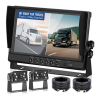
The VEKOOTO N92 system primarily functions as a backup camera and digital video recorder (DVR). It includes a 9-inch monitor and two cameras, allowing for comprehensive rear and potentially side or front views of a vehicle. The monitor displays real-time video feeds from the connected cameras, aiding drivers in maneuvering, parking, and reversing, especially in situations with limited visibility. The integrated DVR capability allows for continuous recording of these video feeds onto a TF card, providing a valuable record of events that can be reviewed later. This feature is particularly useful for accident investigation, security monitoring, or simply documenting journeys. The system supports multiple camera inputs, enabling a broader surveillance area around the vehicle.
Usage Features
The monitor features an intuitive control panel with several buttons:
- MODE: Used to confirm selections or navigate through menus.
- V1/V2: Allows switching between different camera channels, enabling the driver to view feeds from various installed cameras.
- + / -: These buttons are used to increase or decrease values when adjusting display parameters or navigating menu options.
- M (Menu/Return): Accesses the main menu for settings adjustments and also serves as a return button to go back to previous screens.
- POWER: Turns the monitor on or off.
- IR Connector: An interface for infrared functionality, likely for remote control operation.
A remote controller is also provided for convenient operation, mirroring most of the monitor's physical buttons:
- Standby (Power ON/OFF): Controls the power state of the monitor.
- Video Select: Switches between camera channels.
- Menu: Enters the setting page.
- Mode Select: Toggles recording on or off.
- Function Down/Up: Adjusts values or navigates menu options.
The system offers various display and recording settings:
- Time Setting: Allows users to set the current time, which is crucial for accurate timestamping of recorded footage.
- Language: Multiple language options are available for the user interface.
- Screensaver: Configurable to save power or reduce distraction.
- Loop Video: This feature ensures continuous recording by overwriting the oldest footage when the TF card is full. Users can select loop durations (1, 3, 5, or 10 minutes).
- Format: Enables formatting of the TF card, which clears all recorded data and prepares the card for new recordings.
- Picture Settings: Users can adjust brightness, contrast, color, and hue to optimize the display quality according to their preferences and ambient lighting conditions. A reset option is available to revert to default settings.
- Playback: The system allows users to review recorded videos directly on the monitor.
- Split Setting: The V1V2 button can be used to switch between different split-screen modes, allowing simultaneous viewing of multiple camera feeds.
- Function (Mirror): This setting allows users to mirror the image from CH1 or CH2, which is particularly useful for backup cameras to provide a true-to-life reflection of the rear view.
Wiring and Installation
The wiring instructions differentiate between product use and product testing:
For Product Use:
- Yellow Wire: Connects to a positive power source (12-35V).
- Red Wire: Connects to the ACC (Accessory) wire of the car's ignition. This ensures the device automatically powers on when the car key is turned on and powers off when the key is turned off.
- Black Wire: Connects to a negative power source, ground, or sheet metal.
- Blue Wire (CH2 Trigger): Connects to the reversing light. This enables the screen to automatically switch to the camera connected to CH2 when the vehicle is put into reverse.
For Product Test:
- Yellow and Red Wires: Connect together to a positive power source (12-35V).
- Black Wire: Connects to Ground.
- Blue Wire: Can be ignored during testing.
It is strongly recommended to test the system before full installation to ensure all components are functioning correctly, displaying images as expected, and saving valuable time.
Trailer Installation:
For trailer applications, the manual notes that extension cables can be provided. Users are advised to contact VEKOOTO with their Amazon Order ID and the required cable length in feet. The cables feature a rotating button for easy disconnection and extension.
Physical Installation:
- Monitor Installation: The monitor can be installed using a ceiling bracket.
- Monitor Brackets: The monitor brackets are assembled to secure the monitor in place.
- Camera Installation: The cameras are mounted, typically at the rear of the vehicle, to provide the desired viewing angles.
Maintenance Features
The manual includes a "MENU FAQ" section that addresses common issues and questions, serving as a basic troubleshooting guide:
- Returning to Interface: Explains how to navigate back to the main monitor page from the video list or other menu screens using the M/V1V2 or Menu buttons.
- Rotating Image: Guides users on how to adjust image orientation through the "Menu-Setting Rotate" or "Function CH1 Mirror/CH2 Mirror" options.
- Recording Video: Instructs users to press the "MODE" button to initiate recording, indicated by a red point on the screen.
- Trigger Wire Function: Clarifies that connecting the blue trigger wire to the reversing light enables automatic camera switching when reversing.
- Finding TF Card Video: Explains that recorded videos on the TF card can be accessed by plugging the card into a computer using a card reader.
- "No Signal/Black Screen" Troubleshooting: Provides a checklist for resolving display issues, including verifying power supply (12-35V), checking camera power, inspecting wire connections for tightness and correctness, and examining the pins of the monitor and 4-pin camera cables for damage or misalignment.
Important Notes for Installation and Use:
- Confirm battery voltage is between 12-35V before connecting.
- Ensure proper insulation between power cables to prevent short circuits.
- The yellow wire must be connected to the ignition wire for the ignition switch function to work.
- When installing 4-pin cables, align each pin carefully to avoid damage.
The manual emphasizes contacting Vekooto@outlook.com for any questions or assistance, reinforcing their commitment to customer support.