Do you have a question about the Velleman DVM810 and is the answer not in the manual?
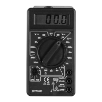
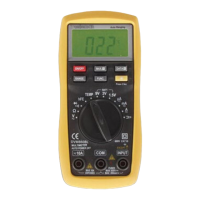
Selects measurement function and range, and activates the instrument. Turn to OFF when not in use.
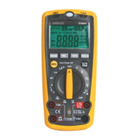
Features a 3 1/2 digit LCD display with 7 segments, 0.5" (12.7mm) height for readings.
Input jack for the black (-) test lead connection.
Input for red (+) test lead for voltage, resistance, and current (excl. 10A).
Input for red (+) test lead for all 10A current measurements.
Socket for hFE measurements of NPN or PNP transistors via b.e.c. connections.
Details accuracy, resolution, and overload protection for DC voltage measurements.
Details accuracy, resolution, overload protection, response, and frequency range for AC voltage.
Details accuracy, resolution, overload protection, and measuring voltage drop for DC current.
Details accuracy, resolution, maximum open circuit voltage, and overload protection for resistance.
Safety precautions to avoid electroshocks and instrument damage during operation.
Step-by-step guide for connecting leads and setting the range for DC voltage measurements.
Instructions for connecting leads and setting the range for AC voltage measurements.
Guide for connecting leads and setting the range for DC current measurements.
Steps for connecting leads and setting the range for resistance measurements.
Procedure for measuring diode forward voltage drop and checking polarity.
Steps to determine and measure the hFE value of transistors using the hFE socket.
| Brand | Velleman |
|---|---|
| Model | DVM810 |
| Category | Multimeter |
| Language | English |