DVM903
V. 02 – 29/01/2020 6 ©Velleman nv
• Disconnect the test leads from the tested circuit before rotating the
range selector in order to change functions.
• When carrying out measurements on a TV set or switching power
circuits, always remember that the meter may be damaged by any high
amplitude voltage pulses at test points.
• Always be careful when working with voltages above 60 VDC or 30 VAC
rms. Keep your fingers behind the probe barriers at all times during
measurement.
• Never perform resistance, diode or continuity measurements on live
circuits. Make sure all capacitors in the circuit are depleted.
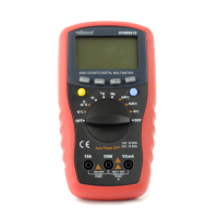
6. General Description
Refer to the illustration on page 2 of this manual:
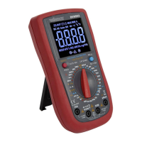
1. Display
3 ½ digits, 7 segments, LCD
2. Function buttons
3. Rotary switch
4. “15A” jack
Insert the red test lead in this connector in order to measure a max.
current of 15 A.
5. “VHz” jack
Insert the red (positive) test lead in this connector to measure voltage,
resistance and frequency.
6. “COM” jack
Insert the black (negative) test lead.
7. “µAmA” jack
Insert the red (positive) test lead in this connector to measure current
(except 15 A).
7. Overvoltage/Installation Category
DMMs are categorized depending on the risk and severity of transient
overvoltage that might occur at the point of test. Transients are short-lived
bursts of energy induced in a system, e.g. caused by lightning strike on a
power line.