8
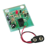
Connect a 9V battery to the holder.
Stand at a location which is certain to have no mains cabling in the vicinity.
Turn the RV1 potentiometer completely to the left (counterclockwise).
Push on the button. Normally the LED should briefly light up.
Adjust RV1 so that the LED is just about dimmed.
The circuit is now adjusted and in its most sensitive position. If one wishes to decrease the circuit's sensitivity, one must turn
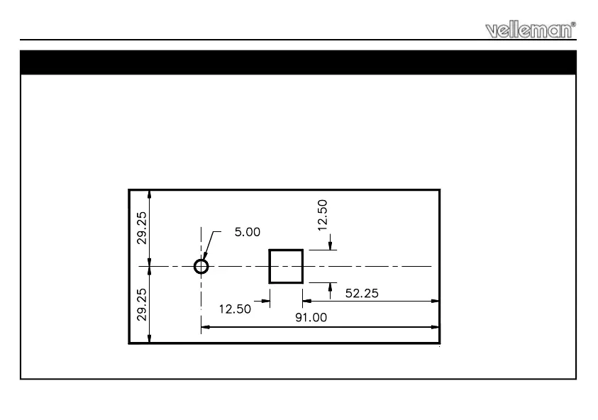
the potentiometer back to the left. The small PCB can be incorporated into the casing type B2646. However, one must then
provide an opening in the covering for the push-button and the LED (see fig.1.0).
Anchor the PCB using two self tapping screws. Finally, cover the push-button with the cap provided.
9. TESTING AND TUNING
Ø
fig. 1.0
Testing and tuning
 Loading...