Do you have a question about the Velleman K8000 and is the answer not in the manual?
Instructions for installing a jump wire component.
Details on mounting 1/2 Watt resistors and their color codes.
Details on mounting 1/4 Watt resistors and their color codes.
Guidance on mounting diodes and verifying their polarity.
Guidance on mounting Zener diodes and verifying polarity.
Instructions for installing integrated circuit (IC) sockets.
Instructions for mounting various types of capacitors.
Instructions for installing a dual in-line package (DIP) switch.
Instructions for mounting resistor trimmers (potentiometers).
Instructions for mounting Light Emitting Diodes (LEDs).
Instructions for installing PCB terminal tabs and connectors.
Instructions for mounting screw terminal blocks.
Instructions for installing the fuse holder and a 250mA fuse.
Instructions for mounting the relay component.
Instructions for mounting 25-pin Sub D connectors.
Details on mounting 1 Watt resistors.
Guidance on mounting electrolytic capacitors and checking polarity.
Instructions for mounting voltage regulators.
Instructions for mounting power transformers.
Instructions for mounting IC chips and checking orientation.
Details on numbering for digital Input/Outputs (I/O).
Details on numbering for Analogue Outputs (DAC).
Details on numbering for Precision Analogue Outputs (DA).
Details on numbering for Analogue Inputs (AD).
Passive tests to perform before computer testing.
Guidance on connecting the card to a computer and peripherals.
| Brand | Velleman |
|---|---|
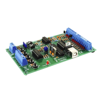
| Model | K8000 |
| Category | Computer Hardware |
| Language | English |