ZFM-70 SeriesFingerprint Identification Module User Manual
www.zhiantec.com Hangzhou Zhian Technologies Co.,Ltd
11
III Hardware Interface
Whether the interface is UART or USB (hardware setting is different when out of factory, please don’t
misuse), on PCB board the connector is same type, 6-pin connector with 1.25mm space between
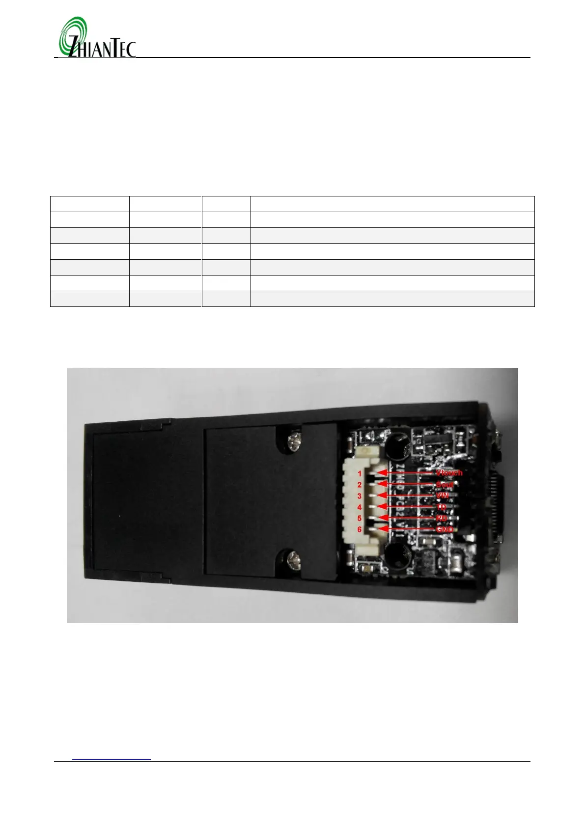
3.1 Serial Communication
When the FP module communicates with user device, definition of pin is as follows:
Touch sensor power input(color: blue)
Touch sensor output(color:yellow)
Data output. TTL logical level (color: green)
Data input. TTL logical level (color: whrite)
Signal ground. Connected to power ground (color: black)
Note: ZFM-706 there is not touch induction function, the pin 1 and pin 2 not connect.
ZFM-708 thers is touch induction function, all pin is valid.
In type ,in means input to module, out means output from module.
Figure 0.1 Serial communicates interface module
3.1.1 Hardware connection
Via serial interface, the Module may communicate with MCU of 3.3V or 5V power: TD (pin 2 of J1)
connects with RXD (receiving pin of MCU), RD (pin 3 of J1) connects with TXD (transferring pin of MCU).
Should the upper computer (PC) be in RS-232 mode, please add level converting circuit, like MAX232, between
the Module and PC.
 Loading...