Do you have a question about the Velotric Nomad Series and is the answer not in the manual?
Lists the tools, wrenches, and spare bolts provided with the bike for assembly.
Details and illustrates the major bike parts such as pedals, reflectors, and lights.
Instructions for attaching the kickstand to the bicycle frame.
Guidance on installing and adjusting the bicycle handlebars.
Procedure for fitting the front wheel and aligning the brake caliper.
Steps for securing the front fender and adjusting its position.
Instructions for correctly attaching the left and right pedals.
How to mount and connect the front bicycle light.
Procedure for mounting and wiring the bike's display unit.
Instructions for installing the bell and front/rear reflectors.
How to set the stem angle for optimal handlebar alignment.
Guidance on inserting and securing the electric bike battery.
Detailed instructions for charging the bicycle's battery.
How to power on the bike and select pedal assist levels.
How to operate the display, lights, and walk mode functions.
Important advice on maintaining correct tire pressure for safe riding.
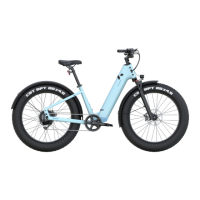
A labeled diagram identifying all parts of the Velotric bike.
Provides website, email address, and phone number for customer assistance.
This document is a Quick Start Guide for the Velotric Nomad Series electric bicycle, providing instructions for assembly, initial setup, and basic operation. It is designed to help users get their new bike ready to ride quickly and efficiently.
The guide begins with a recommendation to follow a video tutorial for bike assembly, accessible via a QR code or a provided URL. This suggests that the assembly process, while detailed in the guide, might be better understood with visual aid, emphasizing ease of use and a smooth setup experience for the user.
The "Contents" section outlines the key areas covered: "What's in the Toolkit," "Bike Assembly," and "Bike Diagram." This structured approach helps users navigate the guide and understand the scope of information provided.
The "What's in the Toolkit" section is comprehensive, detailing all the tools and spare parts included with the bike. The "Tool Bag" contains essential items like a socket wrench, Phillips screwdriver, M15/M8 wrench, M10 wrench, and a set of hex keys (M6/M5/M4/M3/M2.5). The "Spare bolts" section lists specific bolts for the front hub cap/washer, stem clamp, display panel bracket, display panel mount, and fender. Beyond tools and fasteners, the guide also lists other components provided, such as left/right pedals, front/rear reflectors, a bell, an adapter & charging cable, a display unit, a front light, a kickstand, hub caps, and cable binders. This detailed inventory ensures users can verify they have all necessary components before starting assembly.
The "Bike Assembly" section provides step-by-step instructions for various parts of the bike.
This step involves attaching the kickstand. First, the user puts on the hub cap. Then, they unscrew the bolts for the kickstand using the M5 hex key. Finally, the kickstand is attached, and the bolts are tightened. This ensures the bike can stand upright securely.
Assembling the handlebar is crucial for steering and control. The user is instructed to remove four bolts on the clamp using the M4 hex key, then install the handlebar. The handlebar should be adjusted by aligning it with reference marks to ensure proper positioning. The four bolts are then tightened in a specific order (1, 3, 4, 2) as illustrated, which helps distribute pressure evenly and secure the handlebar firmly.
This step focuses on installing the front wheel and aligning the brake system. First, the brake pad spacer is removed from the front brake caliper. Next, the front hub caps are loosened, and the wheel is gently slotted into the fork, ensuring the disc is aligned with the brake caliper pads. Finally, the front hub cap is tightened and secured with a socket wrench to a specified torque of 30-35 Nm. A crucial note warns against accidentally squeezing the brake levers before this step, as it can cause misalignment of the hydraulic brakes. It also mentions that torque can be measured using a torque wrench, highlighting the importance of precise tightening for safety and performance.
Installing the front fender involves several adjustments. The bolts affixing the front fender to the fork top are unscrewed. The support rods are then attached to the fork legs using the M4 hex key. The user is advised to adjust the fender to their preference, ensuring the wheel is centered and there is a clear gap between the fender and the wheel before fastening the bolts. This allows for customization while maintaining functionality.
Attaching the pedals requires attention to their rotational direction. The right pedal is attached to the right crankset by turning it CLOCKWISE. The left pedal is attached to the left crankset by turning it COUNTER-CLOCKWISE. Both pedals are then tightened with the M15 wrench. This step is critical for safe and efficient pedaling.
The front light is attached to its mount. The light's angle is then fixed to a desirable position using a Phillips screwdriver and M8 wrench. Finally, the two front light cables (marked in red) are connected as shown in the illustration, ensuring the light is operational.
Setting up the display involves mounting it and connecting its cables. The bolts on the display's mounting brackets are unscrewed. The display panel is then mounted onto the handlebar and adjusted to an angle that is easily viewable from a riding position. The bolts are tightened with the M3 hex key. The display cables (marked green and blue) are connected, and the display wires are wrapped together with the connected front light cable using a cable binder for neatness and protection.
This step covers the installation of safety features. The bolt on the bell mount is unscrewed, the bell is installed, and its angle is adjusted before tightening the bolt. Similarly, the bolt on the reflector mount is unscrewed, the reflector is installed, and its angle is adjusted before tightening. The rear reflector is attached to the seat post, and its angle is adjusted before tightening the bolt. A note emphasizes that the bell and reflector can be positioned according to user preference, allowing for personalized safety setup.
Adjusting the stem angle ensures proper handlebar alignment. The stem is adjusted to make the handlebar perpendicular to the front wheel. The bolts on both sides of the stem are then tightened, securing the handlebar in the correct position.
Installing the battery is a key step for powering the e-bike. The battery is fitted into the down tube. The key is inserted into the battery lock, and the battery is pressed firmly to nest it. The key is then turned clockwise to lock the battery in place, ensuring it is secure during rides.
This section provides instructions for charging the battery and important safety warnings. The battery can be charged either while in the bike or removed. Before charging in the bike, the bike must be powered off. The battery should be placed on a flat, clear surface. The DC power cord (barrel connector) is plugged into the port, and the adapter is plugged into the wall. The LED indicator will turn red during charging and green when fully charged. The adapter should be unplugged first, followed by the cord from the battery. Warnings include charging the battery in an environment between 50-86°F (10-30°C) and noting that the battery will not charge if the temperature is over 113°F (45°C) or below 32°F (0°C). If outside this range, the battery should be allowed to adjust to room temperature for at least an hour before attempting to charge. The guide also illustrates different LED colors (blue, green, red, flashing red) corresponding to various battery charge levels (80-100%, 50-80%, 5-50%, <5% power).
To start the bike, the protective film is peeled off the display screen. The on/off button is held to power the bike on or off. The system offers five levels of pedal assistance (1=lowest, 5=highest), allowing users to adapt power output to their riding needs. Level 0 means no pedal assist. Each assist level is described:
Once the display is on, users can test various features. Holding the "+" button turns on the front light, and the display dims automatically. Holding "+" again turns off the light, and the display brightens. Pressing "+/-" shifts the pedal assist level up or down. Holding the "-" button activates Walk Mode at 2.5mph (4km/h); releasing the button turns off Walk Mode. These tests ensure all electronic features are working correctly.
Before riding, it is essential to check tire pressure. If the tires feel soft or spongy, they should be pumped up to the pressure indicated on the side of the tire (e.g., 30 PSI, 200kPa/2.0BAR). This maintenance step is crucial for safety and optimal riding performance.
The "Bike Diagram" section provides a visual overview of the Velotric Nomad Series bike, labeling its main components. This includes:
A separate diagram focuses on the handlebar components: a. Brake Lever b. Throttle c. Remote d. Bell e. Shifter f. Grip g. Display
This comprehensive labeling helps users identify parts mentioned in the assembly instructions and understand the overall structure of their e-bike.
The final pages include a motivational phrase, "Define Your Adventure," and "Contact" information for Velotric, including their website, email, phone number, and customer service hours (Monday-Friday, 7 AM-6 PM PST). This provides users with support resources should they encounter any issues or have further questions.
Overall, the Velotric Nomad Series Quick Start Guide is a user-friendly document that systematically walks new owners through the assembly, setup, and initial operation of their electric bicycle, emphasizing safety, functionality, and ease of use.
| Frame Material | 6061 Aluminum Alloy |
|---|---|
| Suspension | Front Suspension Fork |
| Brakes | Hydraulic Disc Brakes |
| Max Load | 440 lbs |
| Pedal Assist Levels | 5 Levels |
| Throttle | Half-Twist Throttle |
| Extras | Integrated Lights, Fenders, Rear Rack |
| Category | Electric Bicycle |
| Motor | 750W Hub Motor |
| Battery | 48V Lithium-Ion |
| Range | Up to 55 miles |
| Tires | 26" x 4" Fat Tires |
| Display | LCD Display |