EasyManua.ls Logo

Velux KFK 100 User Manual

Velux KFK 100
36 pages
To Next Page IconTo Next Page
Page #1 background imageLoading...
Page #1 background image
VAS 453812-2019-11
KFX 210/211/212/213/214
KFC 210/220
For information on VELUX smoke ventilation, please contact your VELUX sales company:
Tel. 01592 778 225 (UK), Tel. 01 848 87 75 (IE)
SMOKE
VENTILATION
25-09-2014 07:44:14
Instructions for VELUX control
system for smoke ventilation
ENGLISH
Question and Answer IconNeed help?

Do you have a question about the Velux KFK 100 and is the answer not in the manual?

Velux KFK 100 Specifications

General IconGeneral
Power SourceBattery
MaterialPlastic
ColorWhite
CompatibilityVelux Windows
Control MethodRemote Control
Installation TypeWall-mounted

Summary

Important Information

Safety Precautions

General safety warnings, user responsibilities, and essential precautions for operating the system.

Installation and Maintenance Guidelines

Requirements for certified installers and procedures for regular system maintenance.

Break-Glass Point KFK 100

Installation and Connection Procedures

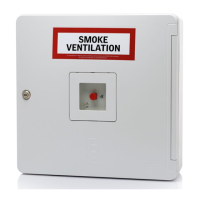
Steps for mounting and wiring break-glass points.

Terminal Module J1 Configuration

Jumper placement for monitoring break-glass points.

Smoke Detector KFA 100

Installation and Connection Guide

Procedures for fitting and wiring smoke detectors.

Terminal Module for Detector Monitoring

Jumper placement for monitoring smoke detectors.

Rain Sensor KLA 200

Rain Sensor Connection Details

Cable specifications and connection method for the rain sensor.

Ventilation Switch KFK 200

Ventilation Switch Wiring

Wiring the ventilation switch to the control system.

Motor Terminals Configuration

Wiring and Cable Specifications

Control Unit Switch Settings

Switches 1-3: Error and Alarm Functions

Configuration of switches for error indication and alarm response.

Switches 4-5: System Configuration

Settings for time-controlled closing and battery monitoring.

Control Unit Operation and Signals

Fire Alarm Activation via Break-Glass

How to activate fire alarm and system response.

LED Indicators and System Status

Meaning of yellow and green LEDs for status and errors.

Comfort Ventilation Button Controls

Using buttons for window opening, closing, and stopping.

Back-up Battery System

Mains Connection Procedure

System Status and Error Indications

Connecting Multiple Control Units

Related product manuals