4
WIRING DIAGRAMS
MKIS00744-040-EN
Vemer S.p.A.
I - 32032 Feltre (BL) • Via Camp Lonc, 16
e-mail: info@vemer.it - web site: www.vemer.it
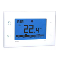
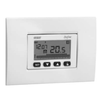
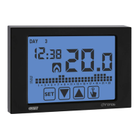
Mod. KEO-A LCD
KEO-B LCD
1
User Manual
ELECTRONIC THERMOSTATS
Read all instructions carefully
Flush-mounting electronic thermostats for temperature control both in heating
and cooling. They perform actions of type 1B and are intended for operating in
environments with Pollution Degree 2 and Overvoltage Category III (EN60730-1).
• Keo-B LCD, with battery power supply and configurable auxiliary input for
the connection of a temperature probe or an external contact with whom to
reduce the setpoint of 3°C.
• Keo-A LCD with mains power supply.
Code Model Description
VE267100 Keo-B LCD Battery thermostat with auxiliary input
VE558300 Keo-A LCD 230V Thermostat
SAFETY WARNINGS
During product installation and operation it is necessary to observe
the following instructions:
1) The device must be installed by a qualified person, in strict compliance with the
connection diagrams.
2) Do not power or connect the device if any part of it is damaged.
3) After installation, inaccessibility to the connection terminals without appropriate
tools must be guaranteed.
4) The device must be installed and activated in compliance with current electric
systems standards.
5) Before accessing the connection terminals, verify that the leads are not live.
6) In the electrical system of the building where the device must be installed, a
protection device from the overcurrents must be present (for KEO-A LCD only).
TECHNICAL SPECIFICATIONS
• Power supply Keo-B LCD: – 2 alkaline batteries 1.5 V (AAA type)
– battery life: 12 months
– depleted batteries indication
• Power supply Keo-A LCD: – 230 Vac (-15% ÷ +10%) 50/60 Hz
– max absorption: 6 VA / 230 Vac
• Installation on 3 modules box (503 type)
• Terminals Keo-B LCD:
– 3 terminals for 1.5 mm
2
cables for output relay 5 A / 250 Vac
– 2 terminals for 1.5 mm
2
cables for digital input (3°C setpoint reduction)
• Terminals Keo-A LCD:
– 3 terminals for 1.5 mm
2
cables for bistable output relay 5 A / 250 Vac
– 2 terminals for 1.5 mm
2
cables for power supply
• Operating mode: summer/winter/off (with antifreeze)
• Password protected lock keypad
• Regulation type:
– on/off with settable differential (0.1°C ÷ 1°C)
– P8 proportional with 0.8°C band (-0.3°C ÷ 0.5°C) and period 8 minutes
– P15 proportional with 1.5°C band (-0.7°C ÷ 0.8°C) and period 15 minutes
• Measurement precision: ± 0.5 °C
• Measurement temperature resolution: 0.1°C
• Setpoint range: 2°C ÷ 50°C
• Operating temperature: 0°C ÷ 50°C
• Storage temperature: -10°C ÷ 65°C
• Operating humidity: 20 ÷ 90% non condensing
• Protection degree: IP40
• Insulation: reinforced among accessible parts (frontal) and all other terminals
REFERENCE STANDARDS
Compliance with Community Directives
2014/35/UE (LVD) 2014/30/UE (EMCD)
is declared with reference to the following harmonized standards: • CEI EN 60730-2-9
06-2023
2
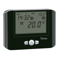
DESCRIPTION
“Environment temperature”
field
“Off”
field
“Heating activation”
field
“Cooling activation”
field
“Active night reduction”
field
Key
“▲” increases the selected field - night reduction activation
Key
“▼” decreases the selected field
3
DIMENSIONS
50
72
50
53
Keo-A LCD Keo-B LCD
5
INSTALLATION
• Install the thermostat in a 3-module flush-mounting box (type 503) at a height
of about 1.5 m above the floor in an area which respects as much as possible the
average temperature conditions of the whole room. Avoid installation near doors
or windows, in niches, behind doors and curtains or in positions with excess or total
lack of ventilation, in order to prevent the temperature reading measured by the
probe from being somewhat offset.
• Install the white or anthracite grey front panel according to your preferences by
hooking it to the cogs of the device (with series BTicino Living Now use the
front panel included in the dedicated kit, see BOX 9).
• Make the connections by respecting the diagrams described in this manual.
• Fix the device inside the 3 modules box in compliance with the assembly diagrams
described on the back of this instruction sheet. The installation accessories
included in the package or can be purchased separately (see BOX 9) allow for
adaptability with the main domestic range.
7
BATTERY REPLACEMENT (Keo-B LCD only)
The extraction of the device, to access the battery compartment, takes place by
pulling on the convexity of the front panel.
In the event of low batteries, the device display will alternately show:
Replace the batteries as soon as possible!
Dispose of batteries in the appropriate recycling containers.
Default values
Heating setpoint
21 °C
Cooling setpoint
25 °C
Minimum settable setpoint - L0
2 °C
Maximum settable setpoint - Xi
50 °C
Operating mode
(heating)
Antifreeze temperature 6 °C
Regulation type On /Off
Differential 0.3 °C
Auxiliary input DIG
Password - - - (desabled)
3 sec.
6
RESET
Reset to delete the settings you made and reload the default values. To reset:
1 remove and restore power to the device (Keo-A LCD) or remove it from the base
and re-insert it (Keo-B LCD).
2 during the flashing of the backlighting press the keys and
until DEf
will appear.
information to users pursuant to art. 14 of the directive
2012/19 / EU of the european parliament and of the council
of 4 july 2012 on waste electrical and electronic equipment (WEEE)
If the crossed-out bin symbol appears on the equipment or packaging,
this means the product must not be included with other general waste
at the end of its working life.
The user must take the worn product to a sorted waste center,
or return it to the retailer when purchasing a new one.
Products for disposal can be consigned free of charge (without any new purchase obligation)
to retailers with a sales area of at least 400 m
2
, if they measure less than 25 cm.
An efficient sorted waste collection for the environmentally friendly disposal of the used device, or its
subsequent recycling, helps avoid the potential negative effects on the environment and people’s health,
and encourages the re-use and/or recycling of the construction materials.
COM
NO
NC
N
L
230V~
AUXILIARY
IMPUT
Keo-A LCD Keo-B LCD
COM
NO
NC
1 2 3
4 5
1 2 3
4 5
EST