Do you have a question about the VENDINGBOX 540 and is the answer not in the manual?
The Vending-Box Model 540 is a robust and versatile dispenser designed for ease of operation and maintenance in industrial settings. Its modular construction allows for quick restoration of functionality in case of malfunction, with main components like the power supply unit, drive, and door easily replaceable.
The Model 540 operates as a self-service vending machine, dispensing products stored within its rotating feeder. Users interact with the device via a panel, which includes a controller and various indicators. The machine supports multiple communication interfaces (ETHERNET, WLAN, GSM) for remote management, data transfer, and time synchronization. It can be configured to accept proximity cards for user login and product dispensing.
The core function involves storing and dispensing items from a rotating feeder. The feeder's construction allows for easy configuration to adjust the size of the item storing cells, accommodating up to six different product cell sizes per level. This flexibility ensures that the machine can be adapted to various product dimensions. The dispensing process involves the controlled opening of sliding flaps, which ensure secure product availability.
The device's software manages product inventory, user interactions, and communication with external systems. It can download current time from configured servers, verify time settings, and manage network connections (WLAN, GPRS, VPN). After successful startup and configuration, the dispensing application initiates, presenting a waiting screen for user login via a proximity card.
General Information:
Dimensions:
Permissible Work Temperature Range:
Relative Humidity:
Power:
Communication Interfaces:
Accepted Proximity Cards:
Feeder Configuration (Product Cell Dimensions): The feeder can be configured with various cell sizes. The chart below shows available types with dimensions and number of cells for each type setting:
| Number of cells | A (mm) | B (mm) | C (mm) | D (mm) |
|---|---|---|---|---|
| 540 | 80 | 75 | 275 | 15 |
| 270 | 80 | 150 | 275 | 30 |
| 270 | 170 | 75 | 275 | 15 |
| 180 | 260 | 75 | 275 | 15 |
| 135 | 170 | 150 | 275 | 30 |
| 90 | 260 | 150 | 275 | 30 |
*Maximum load of a single loading shelf: 0.5kg. **Version with extended range of working temperatures. ***Average power consumption/maximum momentary power consumption.
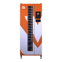
General View and Construction: The dispenser features a monolithic, cubic construction with a double-leaf, asymmetrical front door. The left door, opened with a key, provides access to sliding flaps controlling feeder cell availability and houses the electromechanics for flaps and steering electronics. The right door, secured by two safety screws, contains the user panel controller and the panel itself. Two antennas for radio communication are located on the upper cover, requiring clear surroundings for proper function. The lower part of the device houses the power supply unit, main driver, drum brake, and drive module. The central element is the rotating feeder, which stores items and can be easily configured.
Inner Front Panel: All switches and use sockets are located on the front panel at the bottom of the machine. Key components include fuse sockets (F1, F2, F3), a main switch, a switch for semi-automatic feeder rotation, a right door opening sensor, and a VNET gate address adjuster.
Back of the Device: The back of the machine features connection sockets for power supply, ETHERNET, and VNET bus for subordinate devices. A rating plate identifies the device and its parameters.
User Panel Controller: The user panel controller is located inside the right door, accessible by removing the cover. It includes a SIM card socket and a micro SD card slot.
Starting the Device: The device undergoes a startup sequence upon power-on, including self-tests, checking power supply, verifying communication interfaces (ETHERNET, WLAN, GPRS), synchronizing time, and checking VPN connection. The system indicates status through icons and sound signals.
Configuration of the Feeder: Product cells can be individually adjusted in size, even while the machine is in use. Six different sizes are available. Cell type must be set for the entire level, not for individual cells within a level. Changing cell width requires proper adjustment of the element defining the opening width of the sliding flap.
Loading and Downloading Products: Products can be loaded manually or in mass. The loading process involves opening flaps and placing products into cells. The system indicates the status of flaps (locked, unlocked, ready) through LED colors. The device supports various product categories and allows for selection based on type and quantity.
Switching Off the Device: To switch off, the main power supply switch must be turned to the '0' position. In emergencies, the machine can be unplugged. An internal battery provides temporary power to the user panel controller, emitting a sound signal for about a minute to indicate power disconnection. If power is restored within this minute, the machine resumes operation. If not, it fully switches off. The battery also ensures data integrity during power outages.
Cleaning and Conservation: The device requires regular cleaning with a damp cloth and non-aggressive detergent. Avoid soaking electronic components. Regular checks of drum rotation and flap movement are essential to ensure smooth operation. Rails should be lubricated occasionally to reduce friction. The mechanism blocking feeder rotation should also be controlled.
Periodic Inspection: A warranty periodic inspection is required every 12 months to check internal mechanisms like drive, transmission, and electromechanical elements. Information on this inspection is available from authorized service centers.
List of Spare Parts: The producer guarantees full availability of spare parts. Common replacement parts include:
Replacement of Consumable Elements:
Parts for Reconfiguration: To change the dispenser's configuration, additional elements may be needed, including:
| Brand | VENDINGBOX |
|---|---|
| Model | 540 |
| Category | Vending machines |
| Language | English |