5
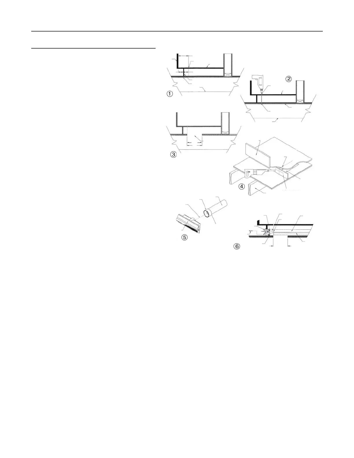
CONNECTION FROM BEHIND
Choose a location under the cabinet for the V600W
VacuSweep inlet valve so that it can be connected
to the central vacuum tube. Measure distance (X)
between the kickplate face and the inside edge
of the cabinet. Then, add 2¾” to the measured
distance. Refer to figure . Measure out the new
distance (X + 2¾”) from the cabinet door, to the
reference mark.
Drill a small reference hole straight down through
to the basement. Refer to figure . Locate the
reference hole in the basement and verify that there
are no obstructions.
Using a reciprocating saw, cut an access hole in the
floor under the cabinet and approximately 8” behind
the location of the V600W VacuSweep inlet valve
reference hole so that the V600W VacuSweep inlet
valve can be connected to vacuum tube by reaching
through the access hole. Refer to figure .
Using the reference hole as a center, cut a
2 ³/
8” H x 6
5
/8” W rough opening in the kickplate
face. Refer to figure .
Insert a coupling (part no. V127) onto the rear of the
housing. DO NOT GLUE this connection (Designed
for friction fit). Refer to figure . Make the terminal
connections to the V600W VacuSweep inlet valve by
sliding the low-voltage wire into wire clips. Turn the
power to the vacuum unit ON to test the connection.
After successful completion of the test, turn power to
the vacuum unit OFF. Insert the V600W VacuSweep
inlet valve into the cabinet base and tube.
With the door in an open position, secure the V600W
VacuSweep inlet valve to the cabinet base using
no. 6 screws. Refer to figure . Ensure that the
spring on the electrical connector has 1/8”
clearance to rough opening. From the basement
reach through the access hole and glue a section
of 2” central vacuum tube to the coupling. Continue
with remainder of central vacuum connections.
V600W VACUSWEEP® INLET VALVE INSTALLATION (CONT'D)
AD0046A
CABINET
KICKPLATE
CABINET
CABINET
DOOR
REFERENCE
MARK
2¾”
X
S
UBFLOOR
JOIST
JOIST
(X) + (2¾”)
R
EFERENCE
MARK
SUBFLOOR
REFERENCE HOLE
SEEN
FROM BASEMENT
CABINET
DOOR
REFERENCE
HOLE
8”
CUT 8” ACCESS
HOLE BEHIND
REFERENCE HOLE
8” ACCESS HOLE
JOIST
CUT A 2/8” H X 6
5
/8” W
ROUGH OPENING USING THE
REFERENCE
HOLE AS CENTER
2” CENTRAL
VAC
PIPE
COUPLING
DO NOT GLUE
THIS
CONNECTION
VACUSWEEP®
I
NLET VALVE
GLUE THIS
CONNECTION
(COUPLING/PIPE)
T
ERMINAL CONNECTIONS
VACUSWEEP®
I
NLET VALVE
2 X NO. 6
SCREWS
DO NOT GLUE
THIS
CONNECTION
8”
ACCESS
HOLE
TERMINAL
WIRES
GLUE THIS
CONNECTION
COUPLING
2” CENTRAL
VAC
PIPE