WIRING
WARNING: THE FAN AND ANCILLARY CONTROL
EQUIPMENT MUST BE ISOLATED FROM THE POWER
SUPPLY DURING THE INSTALLATION / OR
MAINTENANCE.
IMPORTANT
The fan should only be used in conjunction with fixed wiring.
The cross - sectional area of supply cord used should be ranged from 0.75-1.5mm
2
.
Cable entry can only be made from the rear of the fan.
The extraction fan is suitable for connection to 220-240V 50Hz supply.
The fan is a class ll double insulated product and MUST NOT be earthed.
1. Select and follow the appropriate wiring diagram. (Fig. 1 or 2)
2. Check all connections have been made correctly and ensure all terminal connections are securely
fastened.
3. Ensure the impeller rotates and is free from obstructions.
SETUP
WARNING: THE FAN AND ANCILLARY CONTROL
EQUIPMENT MUST BE ISOLATED FROM THE POWER
SUPPLY DURING THE INSTALLATION / OR
MAINTENANCE.
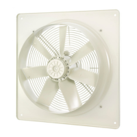
Fixed Speed Range – Fig1, 2, 3, 4 & 5
VASF100B – Basic - Remote or light switch operation. 2 Speed options selectable at install.
VASF100T – Timer* - Overrun timer adjustable 5-30min. 2 Speed options selectable at install.
VASF100HT - Humidity Timer* - Humidity controlled with fixed 15min. timer overrun. 2 Speed option
selectable at install.
Variable Speed Range – Fig1, 2, 3 & 6
VASF100BV – Basic - Remote or light switch operation. Variable speed options selectable at install.
VASF100TV – Timer* - Overrun timer adjustable 5-30min. Variable speed options selectable at install.
VASF100HTV - Humidity Timer* - Humidity controlled with fixed 15min. timer overrun. Variable speed
options selectable at install.
Continuous Running Range – Fig1, 2, 3 & 6
VASF100TC – Timer* - Fixed 15min. overrun timer. Continuous running fan with variable speed options.
VASF100HTC - Humidity Timer* - Humidity controlled with fixed 15min. timer overrun. Continuous running
fan with variable speed options.
*All timer versions require a third switch live wire for the timer to work.