INSTALLATION/USE/MAINTENANCE GUIDE
ISO 9001:2000 - Cert. n. 1368/1
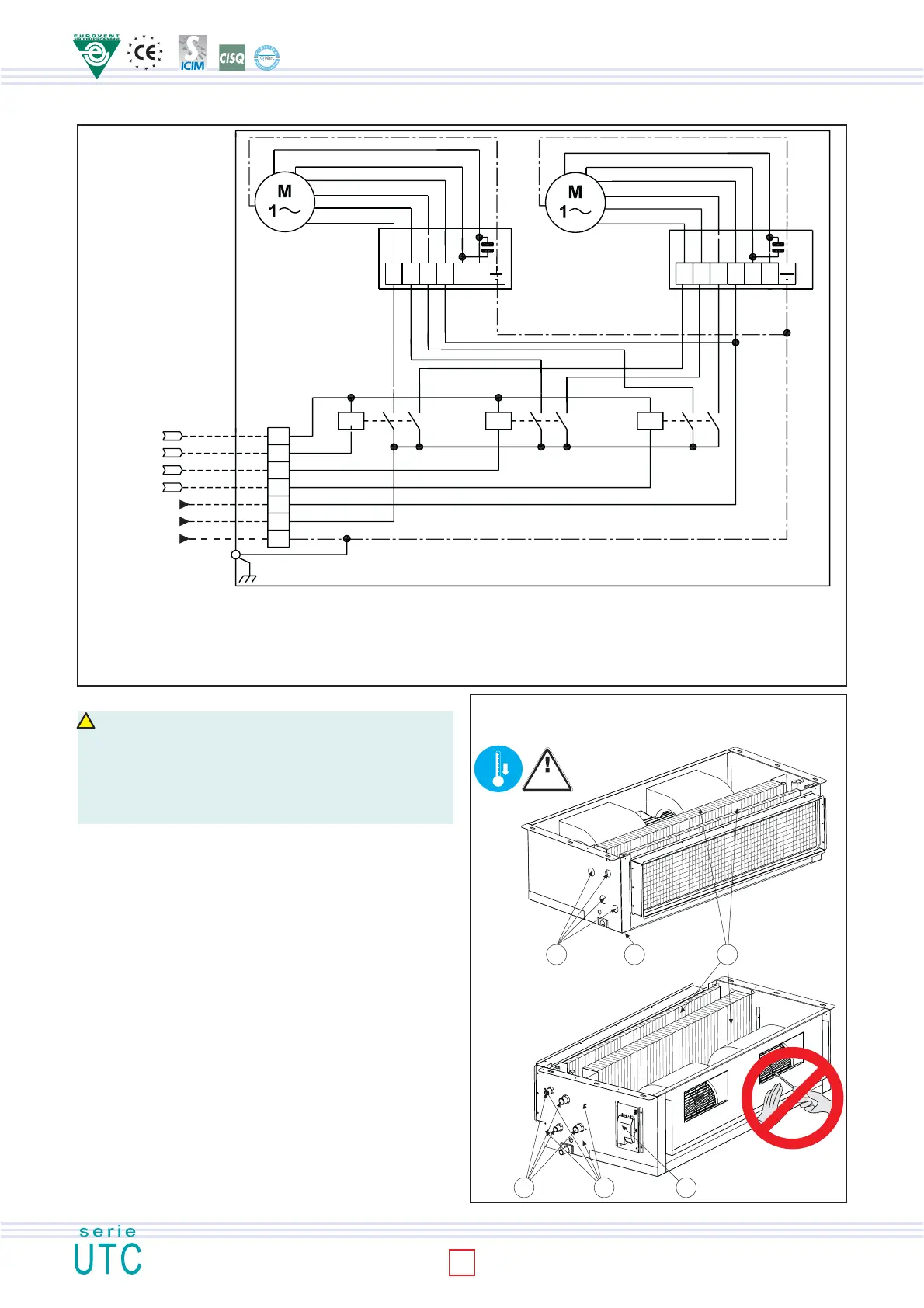
TURNING THE COIL
!
CAUTION
The fan wheels may reach the speed of 1,000 rpm. Do not insert objects into the electric
fan and certainly not hands. The motor becomes hot during operation; wait for it to cool
before touching it. During the heating mode of operation the exchanger and the connecting
pipes may become very hot (80°C). Wait for the exchanger to cool before touching it or
protect hands with suitable gloves. The heat exchange water coils are suitable for working
up to a maximum pressure of 8 bar.
To turn the coil, proceed as follows:
1. Disconnect the terminal board (6) from the side of the unit.
2. Remove the condensate collecting tray (2).
3. Remove the coil fixing screws (5).
4. Take out the coil (3), being careful not to be cut by the fins and not to
damage them.
5. Remove the knockouts (1) on the opposite side of the unit (using a
screwdriver) to allow the coil connections to pass through.
6. Position the coil, turning it without tipping it upside down, so that the fittings
are in line with the holes left by the knockouts.
7. Fix the coil using the previously removed screws (5).
8. Shift the terminal board (fixing it to the side opposite the water fittings) and
the motor cables, fixing them with their clamps. Ensure that the cables pass
through the hole in the side of the unit, protecting them with the relative
grommet. If it proves easier to carry out this operation by separating the
wires from the terminal board, mark the positions of the wires to avoid
making mistakes when reconnecting.
9. Reconnect the wires to the relative terminal board (6), taking care that they
are correctly positioned.
10. Replace the condensate collecting tray (2).
Fig. 18
Fig. 17
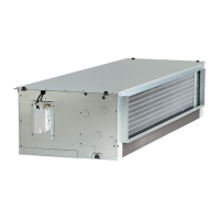
LEGENDA
PE Earth (yellow/green) I Minimum speed
M1-M2 Fan motor II Medium speed
N Neutral III Maximum speed
L Phase SDP Power chart
Com Common (white) XA1-XA2 Connection box
KA1-KA2-KA3 relè 20A/250V type finder 22,22 XA3 Terminal board
1 2
3
45 6
P=8
bar max
0°
60°
230Vac/50Hz
3X2,5 mm
2
Motor power
supply
Remote
control
230Vac/50Hz
4X1,5 mm
2
XA3
blue
black
grey
brown
KA1 KA2 KA3
blue
black
grey
brown
XA2
M2
M1
blue
red
orange
brown
green
yellow
UTC
blue
red
orange
brown
green
yellow
XA1
min med max Com min med max Com
Com
III
II
I
N
L
PE
WIRING DIAGRAM UTC MOD. 70
8
 Loading...