TECHNICAL MANUAL
range
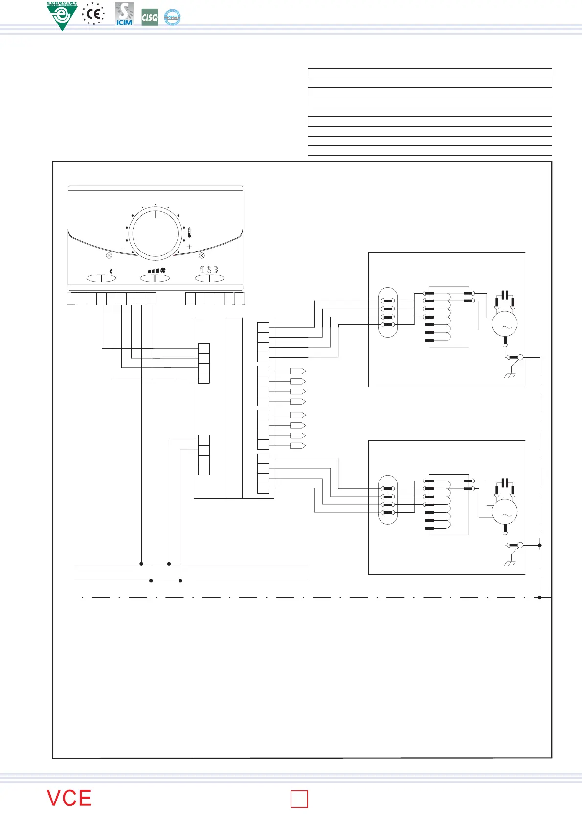
INTERFACE CHART FOR THE CONTROL OF 4 FANCOIL MOD. SDI
DESCRIPTION
By means of the interface chart (to be mounted on DIN bar) it is possible
to control up to 4 facoils with only one thermostat or remote control.
L
N
230 Vac / 50 Hz
PE
Com
9
A
SDI
B'
A'
B
5
6
8
7
Com
II
I
III
4
(interface charte)
1
2
3
15
11
12
10
13
14
III
I
II
18
16
17
20
19
I
II
III
Com
II
I
III
Com
FAN COIL
N° 2
FAN COIL
N° 3
Wire section = 1.5 mmq
F
FILTER
531 2 4
OFF ON
6 7 8 9
A
O
C
M
MODE
1413 15 16 1817
T
R
O
M1
M
L
III
II
Com
XA1
T1
I
4
5
6
2
1
3
M
Fan coil N° 4
C
M
1
Com
I
II
III
I
Com
XA1
II
III
3
T1
6
5
4
L
1
2
M
M
M
M1
1
C
Fan coil N° 1
LEGENDA:
PE PROTECTIVE CONDUCTOR (yellow/green) I MINIMUM SPEED
N NEUTRAL II MEDIUM SPEED
L PHASE III MAXIMUM SPEED
M1 FAN MOTOR T1 AUTOTRASFORMER (not installed in all models)
Com COMMON (white) CD8 REMOTE CONTROL
SDI INTERFACE CHART SDI (for 4 fancoil control) XA1 TERMINAL BLOCK
TECHNICAL DATA
Wlectrical supply: 230V -15% +10% / 1 /50 Hz
Nominal current: 3 A
Voltage rating: 250 V
Protection grade: IP 30
Working temperature: 0-40°C
Humidity limits: 10-80% R.H. (no-condensing)
Container: Tecno-polymer class V0
Dimensions: 105 x 90 x 70 mm
Weight: 316 g
Connection example
ISO 9001:2000 - Cert. n. 1368/1
46
 Loading...