Do you have a question about the Vents BU-1-60 TF and is the answer not in the manual?
Introduces the BU as a multifunctional fan control unit for accommodation spaces and its basic capabilities.
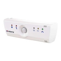
Explains the meaning of LEDs (red, yellow, green) indicating fan status and sensor actuation.
Lists the items included in the package: control unit, user's manual, and package box.
Details voltage, capacity, loading type, protection power, and dimensions of the device.
Specifies the environment temperature and humidity range for device operation.
Outlines crucial safety precautions, including professional installation, air quality, and voltage handling.
Recommends installing the BU under the fan and identifies front panel components like sensors and indicators.
Details the operative range and viewing angle of the moving sensor for optimal placement.
Provides a guide for mounting the BU, including panel removal, drilling, and fixing steps.
Advises on the specific upward movement required for mounting due to the design of the mounting holes.
Specifies switch clearance and recommended wire marking for connections.
Illustrates connection diagrams for different BU models, vital for correct wiring.
Emphasizes performing installation only when power is off and handling electronics carefully.
Guides on opening the fan, connecting the supply wire to the input terminal block, and closing the fan.
Instructs to connect the BU input terminal block according to the provided schemes.
Covers configuring the BU, reattaching the front panel, and turning the unit on.
Explains configuring the hygrostat function using regulators and switch settings, with LED indicators.
Details setting up the photo switch mode for dark conditions, including activation delay and threshold.
Explains configuring the photo switch mode for light conditions, including activation delay and duration.
Describes setting up the outer signal control, including combinations with other modes.
Details how to activate the moving sensor mode, specifying its operating range and activation switches.
Explains setting up the cyclic mode, including fan working and pause times.
Details how to configure time-based parameters using RP1/RP2 potentiometers with specific positions and times.
Explains configuring moisture threshold levels using RP1/RP2 potentiometers with specific positions and percentages.
Specifies recommended temperature, humidity, and air quality for storing the BU.
Outlines the 12-month warranty period, conditions, and exclusions for the BU.
Explains the customer's right to exchange the BU if a fault occurs due to the manufacturer's fault within the warranty period.
Confirms the Fan control unit 'BU-1-60' is compliant with technical specifications and recognized as serviceable.
Provides fields for recording inspector's stamp, seller's name, and selling date for warranty purposes.
The VENTS BU-1-60 X is a multifunctional fan control unit designed for operating fans in various accommodation spaces such as kitchens, bathrooms, and bedrooms. This device offers automatic control functions based on a range of sensors and timers, providing flexible operation modes to suit different situations.
The BU-1-60 X can include, depending on the specific model, an automatic control function based on the use of a moisture sensor (hygrostat), a lighting sensor (photo switch), a motion sensor, a timer, and manual control via inner and outer switches. It also provides a cyclic power on/off function. Users can set various function modes using the integrated switches. For example, in a toilet, the lighting sensor and timer can be used to turn the fan on when someone enters and keep it running for a set duration (e.g., 10 minutes).
The front panel of the BU includes:
Function modes are indicated by LEDs:
Hygrostat (option): The fan turns on when the moisture level exceeds a set threshold, which is configured using the RP1 regulator. A green LED indicates moisture level exceeding and fan activation. After the moisture level drops, the fan continues to operate for a time set by the RP2 regulator. This mode is activated by setting switches 1 and 2 to the ON position.
Photo Switch (Dark): The fan turns on 5 seconds after the room light turns OFF. The fan's working time is set by the RP2 regulator. The operating threshold is set by the RP1 regulator. A yellow LED indicates illumination threshold exceeding. This mode is activated by setting switch 1 to the ON position.
Photo Switch (Light): The fan turns on 10 seconds after the room light turns ON. After the light turns off, the fan continues to work for a time set by the RP2 regulator. The operating threshold is set by the RP1 regulator. A yellow LED indicates illumination threshold exceeding. If the light remains on for over 60 minutes, the fan turns off. This mode is activated by setting switch 2 to the ON position.
Outer Signal Control: The fan turns on 3 seconds after activation by an inner or outer switch. It continues to operate for a time set by the RP2 regulator. This mode is activated by setting switch 3 to the ON position and can be combined with hygrostat and photo switch modes.
Motion Sensor (option): The fan turns on after detecting movement of a significant object (e.g., a human) within the sensor's operating range (5m distance, 130° viewing angle). After movement ceases, the fan continues to work for a time set by the RP2 regulator. This mode is activated by setting switches 3 and 4 to the ON position.
Cyclic: The fan turns on periodically. It operates for a time set by the RP2 switch and remains off for a time set by the RP1 switch. This mode is activated by setting switches 1, 2, 3, and 4 to the OFF position.
| Brand | Vents |
|---|---|
| Model | BU-1-60 TF |
| Category | Control Unit |
| Language | English |