22344b
C200
8-12-99A
7-22-02B
INSTALLATION DWG
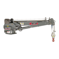
HT40KX, HT50KX
SUPERCEDES
TITLE
DATE
SECTION
ELECTRICAL CONNECTIONS
A 25 ft. electrical power lead - intended for 12V DC only - also comes down through the center
of the quill with the hoses. This lead should be looped in the compartment so that it remains
relaxed throughout the 400 degree rotation of the crane.
A 15amp circuit breaker is mounted on the crane and protects the crane's internal wiring and
solenoid coils. The 15amp circuit breaker does not protect the 25 foot electrical power lead.
For added protection, the 25 ft. lead can be connected to a 15-20 amp protected circuit that, if
possible, is powered only when the vehicle engine is running
HYDRAULIC FLUID
Average Climate Type of Oil
Cold to Moderate ISO Grade AW 46
Warm to Hot ISO Grade AW 68
The fluid should have the highest anti-wear characteristics and treated to inhibit rust and
oxidation.
HYDRAULIC HOSES & LINES
The minimum sizes for lines and hoses are as follows:
PRESSURE 3/8"
RETURN 1/2"
SUCTION 3/4"
RESERVOIR
The PTO reservoir should have a capacity of 10 gallons fitted with 100 mesh suction screen,
10 micron return line filter, and filler/breather cap.
PTO PUMP
The PTO pump should be sized to allow an engine idle speed range that will deliver approxi-
mately 2.5 GPM for the HT40KX standard (non-proportional), 5.0 GPM for the HT40KX pro-
portional, 3.0 GPM for the HT50KX standard or 6.0 GPM for the HT50KX proportional. The
crane's relief pressure is set at 3000 psi.
PTO START-UP
Before connecting the PTO system to the crane pressure and return hoses, connect the PTO
pressure and return lines together at the bulkhead. Operate the PTO system for about two (2)
minutes per gallon of reservoir capacity (in this case 20 minutes) to flush out the lines and filter
all the fluid several times.
ENGINE START/STOP & THROTTLE CONTROL
If your crane was purchased with optional engine start/stop and throttle control, refer to drawing
22615 in the replacement parts section for further information.
CINCINNATI, OHIO
MFG., INC.