Connections
External power supply:
Any 8-15V DC voltage or battery can be connected through the external power interface. The power interface has a
polarity protection circuit to prevent the power supply from damaging the machine.
Headphones:
Connect a stereo headset to the headphone jack (PHONE) with an impedance of 8-32 ohms.
Antenna:
Any resonant antenna can be directly connected to the antenna interface (ANT) with a BNC connector. For non-
resonant antennas, an antenna tuner should be connected between the antenna interface and the antenna.
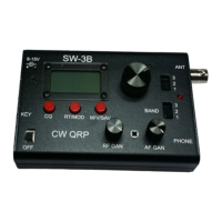
Key/Paddle:
Automatically recognizing the electronics key and the straight key. Just connect the straight key to the mono plug or
connect the middle ring of the stereo plug to the ground below as shown below. When the power is turned on, the
circuit will be based on the inserted key. Different automatic detection is performed. When you hear a click (Morse
code letter A), it is an electronics key, and you hear a click (Morse code letter M) as a straight key. (Be sure to insert
the hand button into the socket before turning on the power to enter the hand button function).
3.5mm Stereo plug
paddle dit or straight key
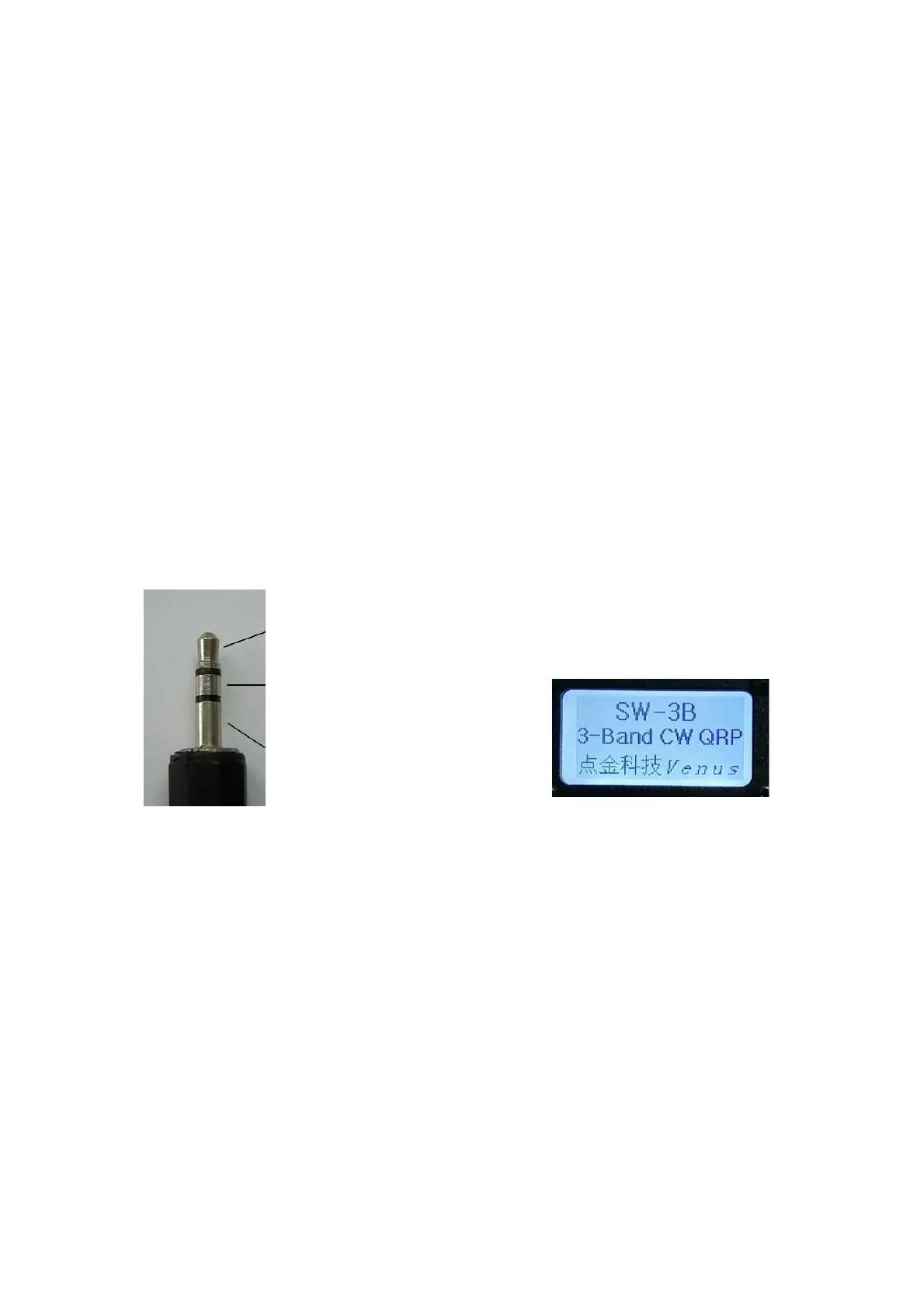
paddle dat or straight key GND Boot screen
paddle GND/straight key GND
Operating
Power Switch and Gain Control:
The power switch is located in the lower left corner of the panel. The RF GAIN and AF
GAIN knobs on the radio panel are the front-end high-frequency gain control and audio
gain control, respectively, clockwise to the maximum gain.
Band Selection:
Two toggle switches on the right side of the panel BAND are band selection switches,
and the two wave switches are linked. The switch positions 1, 2, and 3 correspond to
the 40m, 30m, and 20m bands, respectively. Each band has 8 storage frequency points,
and the frequency and working mode of each frequency point can be set by the user.