This document serves as an installation manual for the Vermeiren Carpo 3 and Carpo 4 scooters, including their 3D and 4D variants. It provides essential information for specialist dealers regarding the assembly, adjustments, and maintenance of these mobility devices.
Function Description
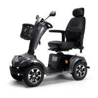
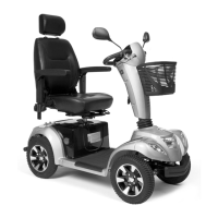
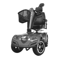
The Vermeiren Carpo 3 and Carpo 4 are mobility scooters designed to assist individuals with limited mobility. They are electrically powered vehicles intended for both indoor and outdoor use, providing a means of independent transportation. The manual details the components and procedures necessary for setting up, adjusting, and maintaining these scooters to ensure safe and optimal operation.
Important Technical Specifications
While the manual does not list exhaustive technical specifications, it highlights several key aspects related to the scooter's design and maintenance:
- Models: Carpo 3, Carpo 4, Carpo 3D, Carpo 4D. The "D" variants likely refer to specific configurations or features, though not explicitly detailed in the provided pages.
- Seat Height Adjustment: The seat can be adjusted in two different heights, with a distance of 25 mm between the settings. This adjustment involves removing a bolt and nut, repositioning an adjustment bar within a receiver, and then re-securing the components.
- Battery Type: The scooters are powered by two batteries. The manual emphasizes that batteries must be replaced by trained personnel and that both batteries should be changed simultaneously to prevent rapid degeneration.
- Tyre Type: The scooters utilize inner tube tyres. The manual provides detailed instructions for changing both front and rear tyres, including procedures for deflating, disassembling the rim, inserting the inner tube, reassembling, and inflating to the recommended pressure.
- Tools Required for Setup:
- Wrench set n° 13, 17
- Allen keyset n° 6, 8
- Safety Features: The manual implicitly refers to safety features through its warnings and instructions, such as ensuring all screws are firmly secured, proper cable routing to prevent pinching, and the importance of the free-wheel lever being in the braking position during adjustments. Antitipping devices are also mentioned as a component (item 15 in the Carpo 3/3D diagram).
- Identification: Each scooter includes an identification plate (item 16 in the Carpo 3/3D diagram). The basic UDI (Unique Device Identification) for Carpo 3 GP is 5415174 122124Carpo 3 GP, and for Carpo 4 GR is 5415174 122124Carpo 4 GR.
Usage Features
The manual primarily focuses on installation and maintenance, but some usage features can be inferred from the component list and adjustment instructions:
- Adjustable Seat: The ability to adjust seat height allows users to customize the scooter for comfort and ergonomic fit.
- Steering Unit with Handgrips and Controls: The presence of handgrips (item 11) and a steering unit (mentioned in scope of delivery) indicates intuitive control for steering and operation.
- Lighting System: Front lights (item 8), indicator lights (item 9), and rear lights (item 14) are included, suggesting suitability for use in varying light conditions and for signaling intentions.
- Storage: A basket (item 12) is provided for carrying personal items.
- Rearview Mirror: A rearview mirror (item 10) enhances safety by providing visibility of the area behind the scooter.
- Freewheel Lever: A freewheel lever (item 13) is present, which is typically used to disengage the motor for manual pushing or to engage the brakes. The manual emphasizes ensuring it is in the braking position during adjustments.
- Footplate: A footplate (item 6) provides a stable and comfortable resting place for the user's feet.
- Armrests and Backrest: Armrests/armpads (item 3) and a backrest (item 2) contribute to user comfort and support.
Maintenance Features
The manual provides detailed instructions for several key maintenance procedures, emphasizing the role of a specialist dealer:
- Assembly and Adjustments: The scooter requires assembly and adjustment by a specialist dealer. This includes securing all screws, preventing objects from getting caught in moving parts, and ensuring proper cable routing.
- Battery Replacement:
- Only trained personnel should replace batteries.
- Avoid contact with battery acid.
- Replace batteries in a well-ventilated room.
- Ensure ventilation holes of the battery housing are clear.
- Always change both batteries simultaneously to prevent rapid degeneration.
- Proper connection of battery cables is crucial.
- The process involves switching off the scooter, removing the seat, lifting the rear plastic cover, loosening straps, unplugging all battery plugs and cable connections, and then lifting out the batteries. Reassembly follows the reverse order.
- Tyre Changing:
- General Precautions: Ensure all air is released before removal, prevent pinching of body parts or inner tube, handle carefully to avoid rim damage, ensure correct tyre pressure, use compliant inflating equipment, and firmly secure all screws with screw adhesive (e.g., Loctite) on the flange, ensuring threads are clean.
- Front Tyre (Carpo 3, Carpo 3D):
- Dismantling: Unscrew the middle screw attaching the tyre to the front fork, release air from the wheel, unscrew the 4 rim screws, and separate the rim sides.
- Assembly: Insert the partly-filled inner tube into the tyre, connect rim sides with 4 screws, put the air valve through the rim hole, reattach the wheel and flange to the front fork with the middle screw, and inflate to recommended pressure. Check for tube pinching.
- Rear Tyre (Carpo 3, Carpo 3D) & All Tyres (Carpo 4, Carpo 4D):
- Dismantling: Unscrew the 4 screws attaching the wheel to the flange, release air from the wheel, unscrew the 5 rim screws, and separate the rim sides.
- Assembly: Insert the partly-filled inner tube into the tyre, connect rim sides with 5 screws, put the valve through the rim hole, reattach the wheel to the flange with 4 screws, and inflate to recommended pressure. Check for tube pinching.
- Documentation: The manual emphasizes the importance of reading the user manual for the scooter, being aware of technical details and limits of intended use, and consulting Vermeiren for more information. It also states that visually impaired people can download an electronic version of the manual.
- Software Changes: Only skilled personnel are permitted to make software changes, considering the user and environment (stability, acceleration, indoor/outdoor use, etc.).
The manual serves as a critical resource for ensuring the correct and safe installation, adjustment, and maintenance of the Vermeiren Carpo 3 and Carpo 4 scooters, highlighting the necessity of professional expertise for many procedures.