Error protection
0000
0001
0010
0011
A1 / C2
OFF
OFF
ON
ON
C1 / A2
OFF
ON
OFF
ON
Unit
Decimal point
Control action
Low limit
High limit
Digit filter
Time scale
Error protection
Security lock
Setpoint offset
Communication ID
Baud rate
: °C
: °F
: Engineer
0000
000.0
00.00 (for linear input signal only)
0.000 (for linear input signal only)
: Dir
: Rev
Refer to table 1.
Refer to table 1.
0.0~99.9
: HH.MM
: MM.SS
0000
0001
0010
0011
0000
0001
0010
0011
0100
0101
0110
-1999~9999 (
=0000)
-199.9~999.9 (
=000.0)
-19.99~99.99 (
=00.00)
-1.999~9.999 (
=0.000)
1~247
: 2.4K
: 4.8K
: 9.6K
:19.2K
°C
0000
Rev
0
1000
0.0
HH.MM
0000
0110
0
247
19.2K
N/A
N/A
N/A
Unit
Unit
Sec.
N/A
N/A
N/A
Unit
N/A
bps
Thermocouple
RTD
0~24 mA
-60~60 mV
-10~10 V
G1
Linked
Open
X
X
X
GA1
Linked
Linked
Linked
Linked
Open
GB1
Open
Open
Open
Open
Linked
GY
Open
Open
Linked
Open
Open
Input signal type
Select the input signal type. The available input signal types are :
Thermocouple : J K T E B R S N C
RTD : PT100 (JIS standard) or PT100 (DIN standard)
Linear : 0~24mA, -60~60 mV or 0~10 V
Please note that the internal gaps on the main board of F4 controller should be configured in
accordance with input signal.
X : don’t care
Figure 12. Gaps Allocation
Low scale for linear input
Select the low scale corresponding to low linear input signal. The default low linear input signal
(INL) for mA, mV and V is 4.00mA, 0.00mV and 0.00V separately. This parameter is only showed
when the input signal type is set to linear. (See also the cut-off function for further detail)
High scale for linear input
Select the high scale corresponding to high linear input
signal. The default low linear input signal (INH) for mA,
mV and V is 20.00mA, 50.00mV and 10.00V separately.
This parameter is only showed when the input signal
type is set to linear. (See also the cut-off function for
further detail)
Cut-off function
The Cut-off function is used to limit the process value of
linear input signal within the boundary whenever the
input signal is out of the high/low limit range (set by Hilt
and LoLt). The cut-off function can be set to “Low”,
“High” or “High/Low”, set to “None” disables the cut-off
function. The cut-off function has no effect for input
signal other than linear input. Figure 13. Scale and Cut-off Function
Only the security lock is open to change, all other parameters are locked
Only the security lock and set point value is changeable. all the other
parameters are locked
The user level is open to change.
The user and alarm levels are open to change.
The user, alarm, and soft levels are open to change.
The user, alarm soft and PID levels are open to change.
All parameters are open to change.
Security lock
0000
0001
0010
0011
0100
0101
0110
Range: 0 ~ 3
Unit: N/A
PV scale calculation:
Where
IN: the linear input signal.
INH: the high calibration of linear input signal. It is set in calibration parameters (mAL, mVL and VL).
INL: the low calibration of linear input signal. It is set in calibration parameters (mAH, mVH and VH).
Example:
For a 4~20mA input signal, the INL is set by mAL=4.00mA and the INH is set by mAH=20.00mA.
Set SCAL=0.0 SCAH=100.0 (Of course, you may select other scale value and decimal point to
alter the resolution) and LoLt=0.0 HiLt=100.0.
For a 12mA input, the PV will be 50.0.
For a 22mA input, the PV will be 112.5 with cut-off function set to “None” or 100.0 with cut-off
function set to “High” or “High/Low”.
For a 0mA input, the PV will be -25.0 with cut-off function set to “None” or 0.0 with cut-off function
set to “Low” or “High/Low”.
Unit
Select the process value indication in °C or °F when the input signal type is set to thermocouple or
PT100. Select engineer unit for linear input (mA, mV or V).
Decimal point
Select the decimal point position. The setting 00.00 and 0.000 is available for linear input only.
Control action
Dir – Direct action used for cooling process
Rev – Reverse action used for heating process
Low limit
Set the low limit of measuring range. When the PV goes below the low limit, the PV display flashing
indicates a low limit error. The control output and alarm will be set according to the Error Protection.
High limit
Set the high limit of measuring range. When the PV goes beyond the high limit, the PV display
flashing indicates a high limit error. The control output and alarm will be set according to the Error
Protection.
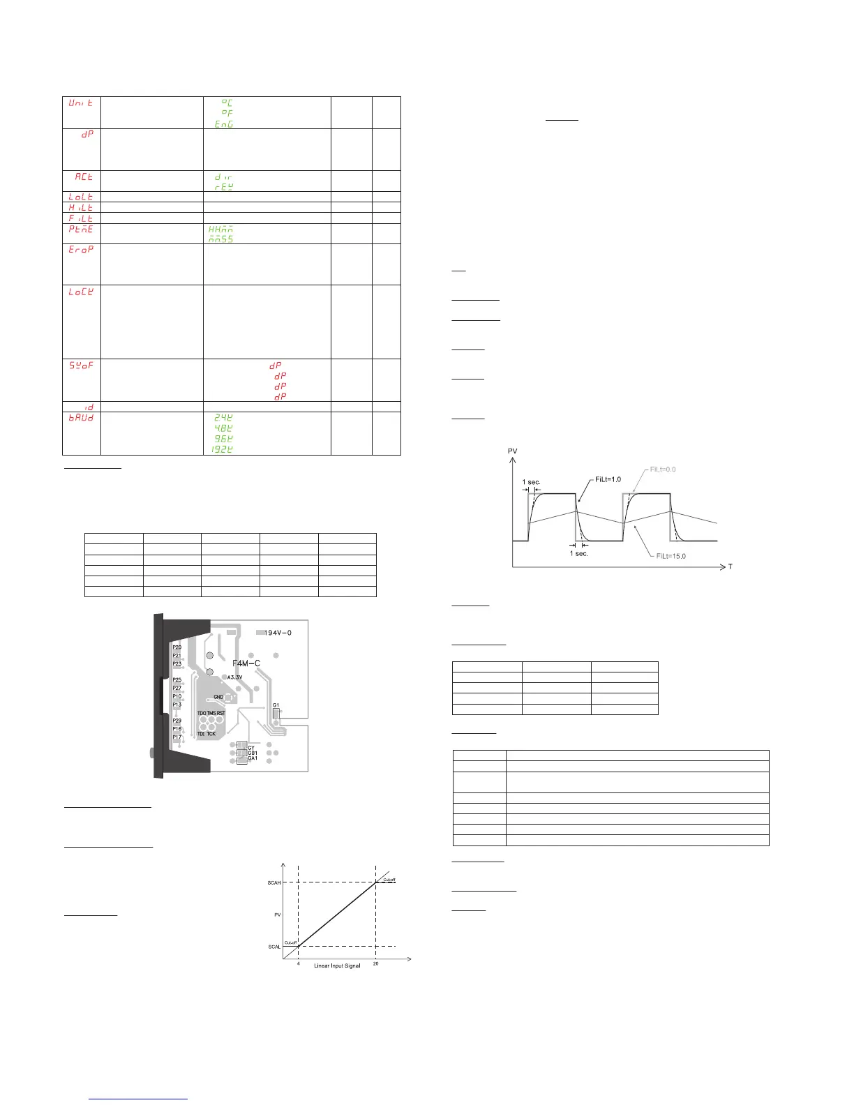
Digit filter
Set the time constant for digit filter (the first order filter). It is useful when the process value is too
unstable to be read.
Figure 14. Digit Filter
Time scale
Set the time scale used for alarm delay time and ramp rate.
HH.MM – The alarm delay time is in hour and minute / The ramp rate is in per minute.
MM.SS – The alarm delay time is in minute and second / The ramp rate is in per second.
Error protection
Set the control output and alarm status whenever an error occurred. (refer to 4 Error Message)
Security lock
The security lock is useful to lock out the parameters from unauthorized changed
Set point offset
Shift the set point value with an offset. The actual control target is shifted with this offset from set
point value but not added to SV display.
Communication ID
Set the ID number in the communication network
Baud rate
Set the communication baud rate.
( )
SCALSCALSCAH
INLINH
INLIN
PV +−
−
−
=
 Loading...