13
ORIGINAL INSTRUCTIONSVES Andover Ltd Eagle Close Chandlers Ford Ind. Est Eastleigh Hampshire SO53 4NF
Tel: 08448 156060 Fax: 02380 261204 E-mail: vesltd@ves.co.uk Web: www.ves.co.uk
Installation, Operation and Maintenance Manual
®
EVC Heat Recovery Unit
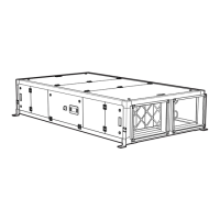
Standard wiring arrangement
Valve Actuator Terminals
Fig.
Standard Wiring
& Fan Installation
5 Continued
SGS65... Valve Actuator
To isolate from the main power supply, the system must incorporate a device which disconnects
all the phase conductors
Warning
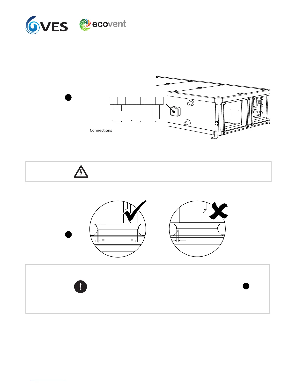
Prior to starting the unit it is important to ensure that the fans are free running, and should
any components have moved during transit take care to ensure they are realigned to allow
correct operation/rotation. A trial spin by hand should indicate if the fan is rubbing. To align,
losen either the fan plate fixings or the inlet ring, adjust and retighten, see figure above.
The same should be applied to any wiring looms which may have become unfastened; ensure
that loose wiring is securely stowed away from any moving components.
The impellers on size zero units are not adjustable; any alignment issues should be reported
to VES.
Fan alignment details
Fig.