EasyManua.ls Logo

VEVOR HL10000 - User Manual

VEVOR HL10000
12 pages
Print Icon
To Next Page IconTo Next Page
Loading...
Technical Support and E-Warranty Certificate www.vevor.com/support
WEIGHT DISTRIBUTION HITCH
MODEL: HL10000
We continue to be committed to provide you tools with competitive price.
"Save Half", "Half Price" or any other similar expressions used by us only represents an
estimate of savings you might benefit from buying certain tools with us compared to the major
top brands and doses not necessarily mean to cover all categories of tools offered by us. You
are kindly reminded to verify carefully when you are placing an order with us if you are
actually saving half in comparison with the top major brands.
Question and Answer IconNeed help?

Do you have a question about the VEVOR HL10000 and is the answer not in the manual?

Summary

Safety Warnings and Precautions

General Warnings

Crucial safety warnings regarding operation, handling, and capacity limits to prevent injury or damage.

General Cautions

Precautions for immediate replacement of defective accessories and regular checks for wear during use.

Product Specifications and Components

Model and Parameters

Details the model number, gross trailer weight, tongue weight, hitch ball size, and shank type.

Components Overview

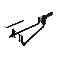
Visual identification of all parts included in the weight distribution hitch system.

Parts List

A comprehensive list detailing each item's quantity and description for the hitch system.

Assembly and Installation Guide

Step 1: Install Shank

Insert the adjustable shank into the tow vehicle receiver and secure it with the hitch pin and clip.

Step 2: Secure Hitch Ball

Torque the hitch ball to the head assembly using a lock washer and nut.

Step 3: Position Head Assembly

Align the head assembly on the shank to achieve the target ball height.

Step 4: Mount Head on Shank

Attach the head assembly to the shank using specified bolts, washers, and nuts.

Step 5: Initial Head Tightening

Lightly tighten the upper bolt connecting the head to the shank.

Step 6: Install Spring Bars

Grease and insert spring bars into the hitch head sockets until they lock into place.

Step 7: Attach Trailer to Ball

Lower the trailer coupler onto the hitch ball and secure the latch.

Step 8: Install Support Brackets

Mark and mount spring bar support brackets onto the trailer's A-frame.

Step 9: Assemble Brackets

Assemble and torque bracket components onto the trailer A-frame.

Step 10: Raise Spring Bars

Lift the spring bars into position by hooking the lift bar into the L-bracket.

Step 11: Secure Spring Bars

Pry spring bars onto L-brackets and secure them with the retainer clip and cotter pin.

Step 12: Adjust Head Angle

Check vehicle height and adjust the head angle using set screws for desired loading.

Step 13: Final Tightening & Check

Tighten all hardware to specified torque values and perform pre-towing checks.

Before You Tow Checklist

A critical pre-towing inspection list for all hitch and trailer connections.

Product Maintenance

General Maintenance Tips

Keep spring bar sockets and pins clean and lubricated; maintain exterior cleanliness and painted surfaces.

Overview

This document describes the VEVOR WEIGHT DISTRIBUTION HITCH, model HL10000, designed to improve towing stability and safety by distributing weight evenly between the tow vehicle and trailer.

Function Description

The VEVOR Weight Distribution Hitch (model HL10000) is a towing accessory designed to distribute the tongue weight of a trailer more evenly across the axles of both the tow vehicle and the trailer. This helps to restore the tow vehicle's front axle load, which is often reduced when a heavy trailer is coupled, leading to improved steering, braking, and overall stability. By leveling the tow vehicle and trailer, the hitch reduces front wheel overload and prevents loss of rear wheel traction, which can otherwise lead to unstable handling, reduced braking ability, and a tendency to jackknife during turns and braking. The system utilizes spring bars that apply leverage to transfer weight from the trailer tongue to the front axle of the tow vehicle and the axles of the trailer. The adjustable shank allows for proper ball height positioning, accommodating various vehicle and trailer setups. The spring bar support brackets are installed on the trailer A-frame, providing attachment points for the spring bars. The snap-up handle facilitates the installation of the spring bars onto the L-brackets, ensuring proper tensioning. The hitch head assembly, which includes the hitch ball, connects to the adjustable shank and provides the sockets for the spring bars. Set screws on the hitch head allow for fine-tuning the angle and, consequently, the weight distribution.

Important Technical Specifications

  • Model: HL10000
  • Gross Trailer Weight (GTW): 10000 lbs
  • Tongue Weight (TW): 1000 lbs
  • Hitch Ball Size: 2-5/16"
  • Adjustable Shank: 2"
  • Hitch Ball Torque: 360 ft-lbs
  • Mounting Plate and Bracket Torque: 45-55 ft-lbs (for 1/2"-13UNC bolts)
  • Main Bolt Torque (3/4" bolts): 200 ft-lbs
  • Set Screw Torque (#13): 50 ft-lbs

Usage Features

The VEVOR Weight Distribution Hitch is designed for straightforward assembly and installation, with clear steps outlined in the manual.

Assembly & Installation:

  1. Shank Insertion: The adjustable shank (#4) is inserted into the receiver tube of the tow vehicle and secured with a hitch pin & clip (#6). The shank can be inverted for high ground clearance vehicles, but ground clearance must be checked.
  2. Hitch Ball Installation: The 2-5/16" hitch ball (#7) is secured to the head assembly (#1) using a lock washer (#8) and hex nut (#9), torqued to 360 ft-lbs.
  3. Head Assembly Positioning: The head assembly is positioned on the shank, sliding up or down to align with the target ball height. The position is marked on the shank.
  4. Head Assembly Fastening: The head is installed on the shank at the marked position. A 3/4"-10 x 5" hex bolt (#10) with a 3/4" conical washer (#11) is inserted through the lower hole in the head channel. The head is rotated forward until the ball is vertical or slightly tilted back; if not, set screws (#13) are adjusted. The second 3/4"-10 x 5" hex bolt (#10) with a 3/4" conical washer (#11) is installed through the upper slotted hole. A second 3/4" conical washer (#11) is placed on both bolts, and 3/4"-10 nylock nuts (#12) are finger-tightened.
  5. Initial Bolt Tightening: The top 3/4"-10 x 5 hex bolt (#10) is tightened just enough to hold the head against the pin in the head channel.
  6. Spring Bar Installation: The round end of each spring bar is heavily greased and pushed into the head socket until a click is heard, indicating it's locked. To release, the spring bar is lifted slightly, and the retaining pin in the hitch head is pulled out.
  7. Trailer Attachment: The trailer coupler is lowered onto the trailer ball using the tongue jack, and the coupler latch is closed. The jack is not fully retracted at this stage.
  8. Tongue Weight Support: The front of the trailer and the back of the tow vehicle are raised approximately 3" with the tongue jack, or until the rear bumper returns to its initial measured height. This facilitates spring bar installation.
  9. Spring Bar Support Bracket Installation: The support brackets (#3) are marked on the trailer A-frame, at least 4" from the end of the spring bars (#2). The mounting plate and bracket are assembled onto the A-frame using two 1/2"-13UNC-4" carriage bolts, two 1/2"-13UNC hex nuts, and spring washers, torqued to 45-55 ft-lbs. The L-shaped bracket is then assembled onto the mounting bracket with two hex nuts and spring washers.
  10. Spring Bar Raising: The spring bar is pulled out from the A-frame, and the lift bar is hooked into the L-bracket.
  11. Spring Bar Securing: The spring bar is pried onto the L-bracket by rotating the lift bar vertically. Once supported, the lift handle is removed, and the spring bar is secured with a retainer clip and cotter pin.
  12. Height Adjustment and Loading: The vehicle height is checked, and the head angle is adjusted using the set screws (#13) until the desired loading is reached. With the spring bars secured, the jack is lowered to apply load to the hitch. The vehicle should settle evenly, and the front and rear bumper reference points are remeasured. Adjust set screws until the vehicle and trailer are level, with spring bars nearly horizontal.
  13. Final Tightening: All 3/4" bolts and lock nuts are tightened to 200 ft-lbs. The set screws (#13) are tightened to 50 ft-lbs. Failure to tighten hardware can lead to fastener loss or failure.

Before Towing: A comprehensive check of all connections is required:

  • Hitch pin & clip (securing shank to receiver)
  • Head to shank fasteners
  • Trailer ball nut
  • Coupler latch
  • Spring bar support brackets
  • Safety chains
  • Lights and turn signals
  • Braking system (including breakaway switch)

Maintenance Features

Regular maintenance is crucial for the longevity and safe operation of the weight distribution hitch.

  1. Lubrication: The socket-mounted ends of the spring bars and the lock pins in the head assembly must be kept free from dirt and well lubricated. Excessive wear in these areas indicates either an overload or inadequate lubrication.
  2. Cleanliness: The exterior of the head assembly should be kept clean, preventing dirt or stones from lodging between the spring bars and the head.
  3. Corrosion Protection: Hitch parts should be painted to prevent rust and maintain a good appearance. Labels should not be painted over.
  4. Lift Bracket Maintenance: Lift brackets should be kept clean and lubricated to ensure ease of operation.

Safety Warnings:

  • Always read and understand all instructions to prevent serious injury.
  • Improper handling of the hand lever grease gun during installation, commissioning, and daily operation can cause various dangers.
  • Improper handling can lead to injury and material damage. The manual should be kept available to operating staff. Country-specific safety measures and accident prevention regulations must be observed.
  • Only qualified persons (due to training, experience, instruction, and knowledge of relevant standards) should assess tasks and identify hazards.
  • Never exceed the vehicle manufacturer's recommended towing capacity.
  • The loaded ball height should never be greater than the uncoupled ball height. Adjust spring bar take-up if the loaded ball height is greater than the uncoupled height.
  • This product is not a toy and should not be used by children.

Cautions:

  • Defective accessories must be replaced immediately to prevent personal injury and material damage.
  • Accessories should be checked for wear, cracks, and other damage during their period of use.

VEVOR HL10000 Specifications

General IconGeneral
BrandVEVOR
ModelHL10000
CategoryAutomobile Accessories
LanguageEnglish

Related product manuals