Do you have a question about the VEXILAR FL-8 and is the answer not in the manual?
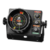
| Display Type | LED |
|---|---|
| Power Output | 400 watts peak-to-peak |
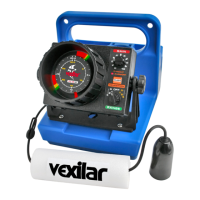
| Type | Fish finder |
| Model | FL-8 |
| Voltage | 12V |
| Battery | 12V, 7 amp-hour |
| Features | interference rejection |
| Power Source | Battery |
| Current Draw | 0.5 amps |
| Display | Three-color LED |
| Beam Angle | 12 degrees |
Details connecting the unit to a 12V power source and wiring recommendations.
Mounting instructions for high-speed transducers on a boat's transom, focusing on water flow.
Method for gluing the transducer to the hull for optimal readings, including test runs.
Explains the control knob for turning the unit on and selecting depth ranges.
Describes the gain control for adjusting signal strength displayed on the unit.
Details setting the alarm point and its function for fish or bottom detection.
Explains how display colors indicate signal strength and target types.
Describes hard bottom indications on the display with predominantly red signals.
Explains challenges identifying bottom/fish in weedy conditions and gain adjustment.
How fish appear as targets, their color changes, and identification challenges.
Differentiates acoustical clutter from electrical noise interference on the display.
How the FL-8 performs at high boat speeds and potential issues with turbulence.
Specific guidance for ice fishing, focusing on bait placement, gain, and fish detection.
Maintenance tips for permanently mounted units, covering connections and transducer care.
Maintenance for portable units, emphasizing wear, tear, and battery condition.
Guidance on setting the gain control for ice fishing and open water fishing for optimal readings.
Explains why bait may not be visible during ice fishing and how to fix it.
Explains that lure reflectivity and shape influence display visibility.
Details how fish colors change on the display based on their position relative to the transducer.
Information on unit run time, battery voltage limits, and battery life considerations.
Explains necessary water contact for depth readings and Ice-Ducer placement.
Confirms the unit reads through clear ice with good contact.
Discusses causes of interference from other equipment and potential solutions.
Guides on which transducer side (flat side) should face the lake bottom.
Explains the zero light as the start of sound transmission and its typical width.
Details how bottom light color and width provide information about bottom type and depth.
Explains bottom indication width is summation of coverage radius and gain control.