VIA Technologies, Inc.
VT82C42
-3-
4. Register
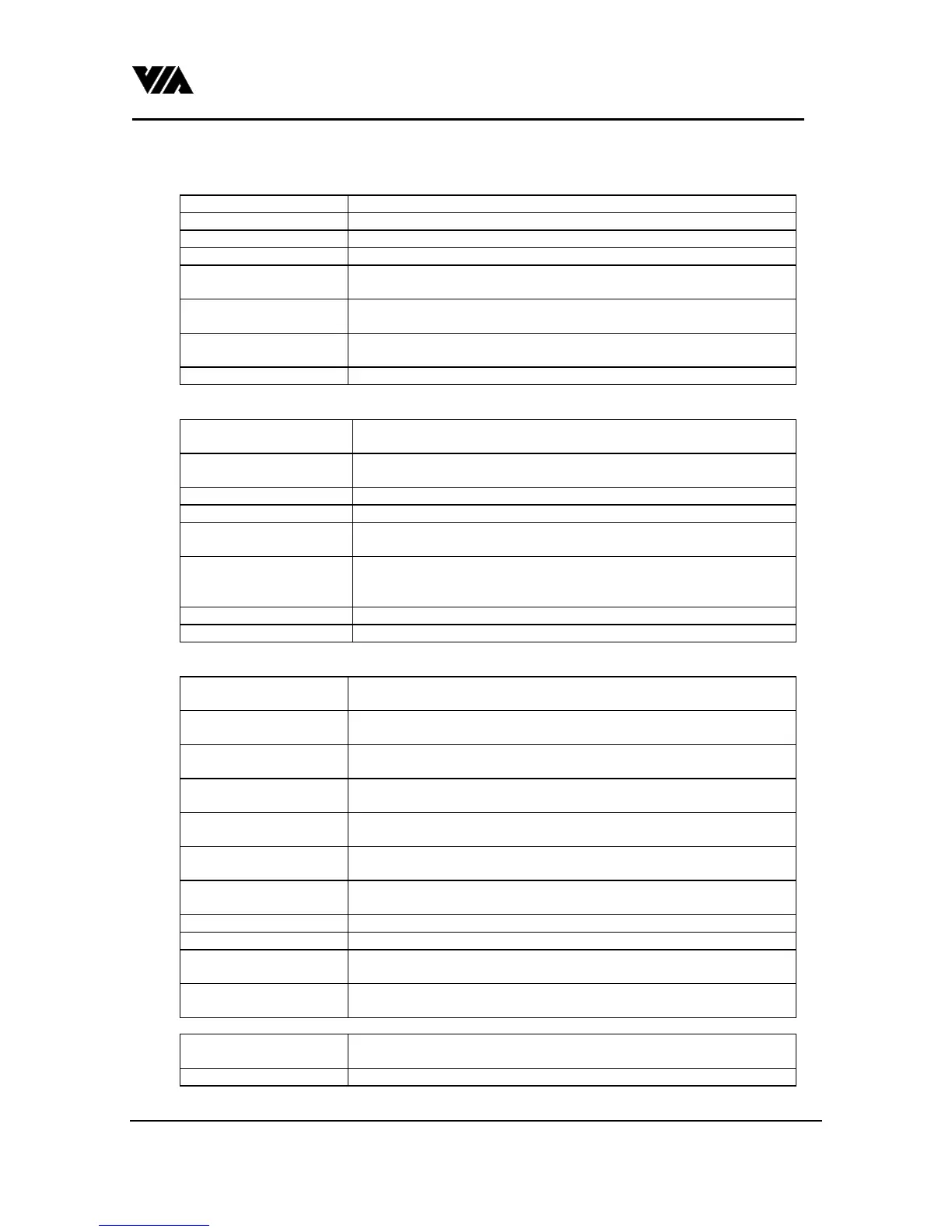
Table 1. Status register: read only (with A0 = 1, CS# = 0, RD# = 0, WR# = 1)
Bit0 : OBF 1 means output buffer is full, 0 means output buffer is empty.
Bit1 : IBF 1 means input buffer is full, 0 means input buffer is empty.
Bit2 : system flag 0 after power on
Bit3 : command/Data 1 means last write is command write. 0 means last write is data write.
Bit4 : keylock status To represent the inhibition of keyboard. 0 means keyboard is inhibited. 1
means keyboard is not inhibited.
Bit5 : transmit time-
out/mouse OBF
Act as transmit time-out on AT mode. 1 means error happens. Act as Mouse
OBF on PS2 mode. 1 means mouse output buffer full.
Bit6 : receive time-
out/general time-out
Act as receive time-out on AT mode. 1 means error happens. Act as general
(receive/transmit) time-out on PS2 mode.
Bit7 : parity error 1 means even parity has occurred in the last transmit/receive.
Table 2. Command register: read/write (use command 20h/60h)
Bit0 : OBF enable 1 means controller will generate high (interrupt) on P24 when output buffer
has been written.
Bit1 : mouse OBF enable 1 means controller will generate high (interrupt) on P25 when mouse data
comes in output buffer.
Bit2 : system flag Connect to the status register Bit2.
Bit3 : inhibit override Write a '1' to this Bit will disable the keyboard inhibit function.
Bit4 : prohibit enabling of
keyboard interface
Write a '1' to this Bit will disable keyboard interface
Bit5 : IBM PC keyboard
type protocol/disable
mouse interface
On AT mode, 0 means that the controller will do a IBM keyboard like
checking on receiving. On PS2 mode, a '1' disable the mouse interface
Bit6 : PC compatible mode Default is 1, means the scan code translation is on.
Bit7 : reserved.
Table 3. Command List: (with A0 = 1, CS# = 0, RD# = 1, WR# = 0)
20h : read command byte
register.
After command execution, OBF = 1 means data is ready on the output
buffer.
60h : write command byte
register.
Next byte write to Data port will be written to command byte register.
9xh : write low nibble to
(Port13-Port10).
A1h : controller's version
number.
After command execution, OBF = 1 means data is ready on the output
buffer.
A4h : check password
command
Always return 'F1' on output buffer.
A7h : disable mouse
interface
After the command execution, Command byte register bit5 = 1 and P23 = 1
on PS2 mode. No effect on AT mode.
A8h : enable mouse
interface
After the command execution, Command byte register bit5 = 0 and P23 = 0
on PS2 mode. No effect on AT mode.
A9h : mouse interface test. Return 00h if the interface is O.K..
AAh : controller's self test Return 55h if the controller is O.K..
ABh : keyboard interface
test.
Return 00h if the interface is O.K..
ADh : disable keyboard
interface.
AEh : enable keyboard
interface.
AFh : return version
 Loading...