VIA Technologies, Inc.
VT82C42
-4-
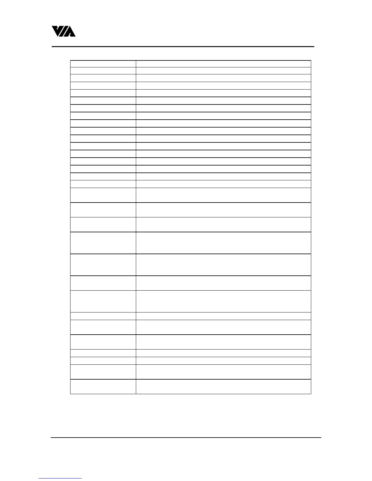
number.
B0h : write 0 to P10.
B1h : write 0 to P11.
B2h : write 0 to P12.
B3h : write 0 to P13.
B4h : write 0 to P22.
B5h : write 0 to P23.
B6h : write 0 to P14.
B7h : write 0 to P15.
B8h : write 1 to P10.
B9h : write 1 to P11.
BAh : write 1 to P12.
BBh : write 1 to P13.
BCh : write 1 to P22.
BDh : write 1 to P23.
BEh : write 1 to P14.
BFh : write 1 to P15.
C0h : read controller's
input ports P17-P10.
C1h : poll input port
low.
Read from P11,P12,P13 and write to status register bit5,bit6,bit7.
C2h : poll input port
high.
Read from P15,P16,P17 and write to status register bit5,bit6,bit7.
C8h : enable D1
command be effective
to P22 and P23.
C9h : disable D1
command be effective
to P22 and P23.
CAh : return on bit0 the
mode value.
1 for PS2 mode, 0 for AT mode.
D0h : return the
controller's output port
P20-P27.
D1h : write output port. The next byte written to data port will be put on output port.
D2h : write keyboard
output buffer
The next byte written in to data port will be put on the output buffer
and OBF = 1.
D3h : write mouse
output buffer
The next byte written in to data port will be put on the output buffer
and mouse OBF = 1.
D4h : write to mouse The next byte written in to data port will be transmit to mouse.
E0h : read test inputs. Return T0 & T1 values on bit0 & bit1 respectively.
Exh : active output
ports
P23-P21 will change according to the status on bit3-bit1.
Fxh : pulse output ports P23-P20 will be pulse low for 6us according to the status on bit3-
bit0.
5. Design Example:
1. To work with AT mode mother board.
 Loading...