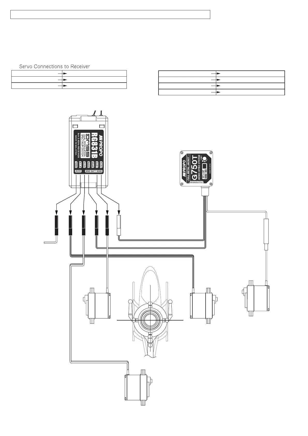
Rudder Servo Servo(output on Gyro)
RUDD(input on Gyro) RUDD
(output on Receiver)
GAIN(input on Gyro) AUX2
(output on Receiver)
ESC THRO
(output on Receiver)
P.8
☆ Wiring Diagram for JR Radios for Flybar Rotor Head
Conrm connections between the servos and the receiver as per the gure below.
The lead harnesses of the servos shown in the diagram are color coded simply for easy distinction.
When using other makes of Radio set refer to their instruction manual to conrm correct wiring.
Gyro and Other Servo Connections
ESC
Receiver
Gyro
Rudder Servo
Swash Servo Rear
Swash Servo Left Swash Servo Right
Swash Servo Rear ELEV output on Receiver
Swash Servo Right AILE output on Receiver
Swash Servo Left AUX1 output on Receiver
ⓐ
Please note that the 'Gyro gain
Lead' may plug into one of several
dierent positions on the receiver -
check your transmitter manual
 Loading...