VIDEO SHIELD
VIDEO SIGNAL
GROUND
-
LENS POT
ZOOM
-,
LENS POT FOCUS
-
CAMERA GROUND
CAMERA 24 VAC
-
CAMERA 24 VAC
-
LENS COMMON
-
LENS IRIS
LENS FOCUS
-
LENS ZOOM
-
i
2
3
4
5
6
7
8
9
IO
I1
12
0
0
0
0
0
0
0
0
0
:
0
-
d
Jl
I
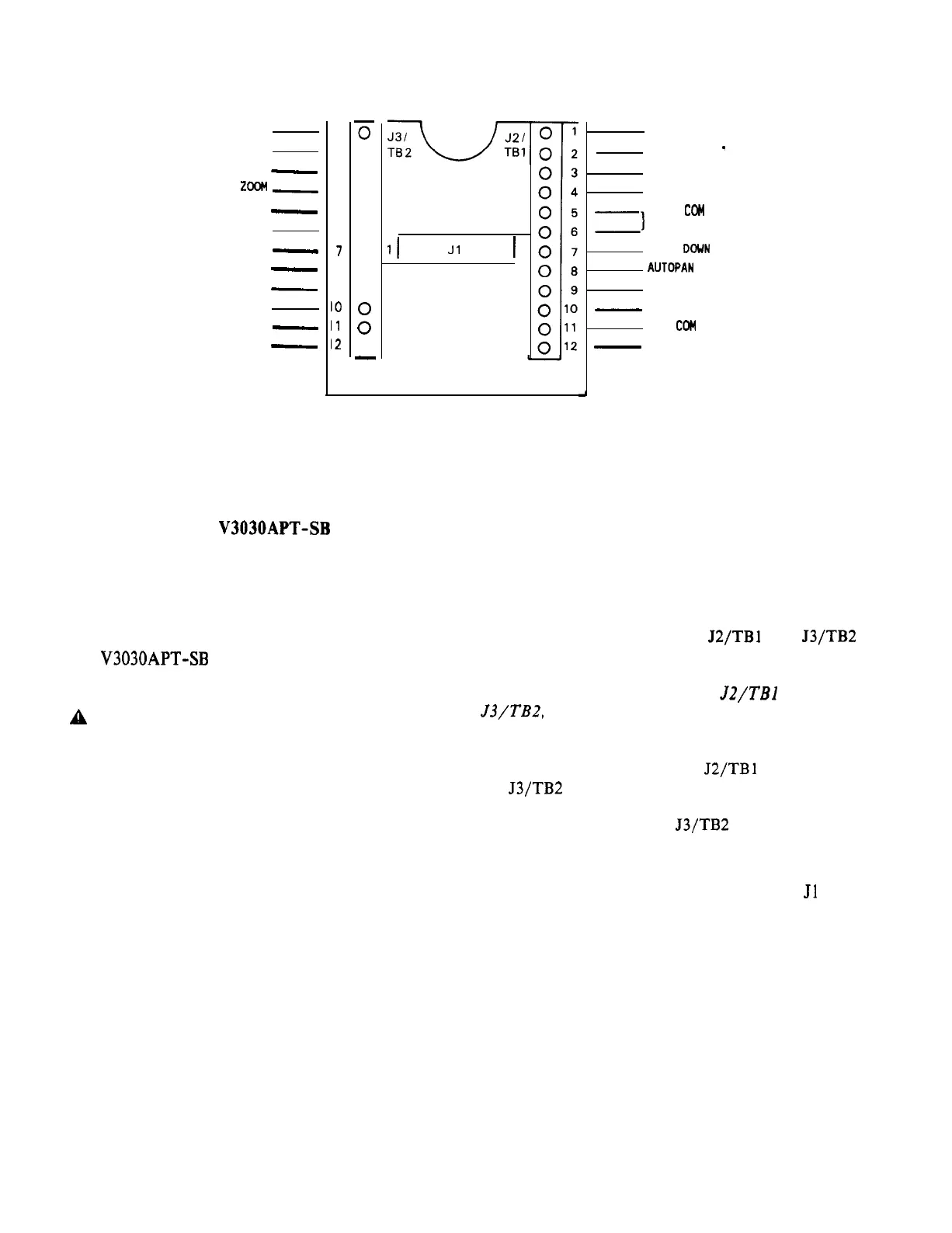
Figure 1
Base Plate/Cable Connections
MOUNTING THE V3030APT-SB
1. Select a suitable mounting location for
the pan-and-tilt. The mounting surface
must provide adequate support for the
combined weight of the pan-and-tilt unit
and the camera/lens combination. [The
V3030APT-SB
weighs 2.2 pounds (0.9 kg).]
CAUTION: The wiring for this unit may be
A
concealed behind the mounting surface and
enter the unit through a hole in that
surface, or it may enter the unit through
the slots in the side of the base. If the
slot is used, ensure that its edge is
smooth, so that the cable insulation is
not damaged.
2. Remove the mounting plate template
provided at the end of this manual
(Figure 7). Position the template on the
selected mounting location and mark the
location of the mounting holes and cable
entry location.
3. Open a hole in the wall for cable entry
for installations where the wiring to the
unit is to be concealed behind the
mounting surface.
4. Pull the video, power, and control cabling
through the cable entry location for
installations where the wiring comes from
behind the mounting surface.
TILT POT C
TILT POT
-
PAN POT C
PAN POT +
Z)
TILT
COM
TILT UP
TILT
DOWN
AUTOPAN
PAN RIGHT
-
PAN LEFT
PAN
CCM
-
GROUND
5. Detach the base plate from the
pan-and-tilt by removing the two (2)
screws.
See Figure 1.
6. Strip the wire ends a quarter of an inch
and loosen the screws of J2/TBl and J3/TB2
(see Figure 1).
NOTE: When routing wires to
J2/TBl
and
J3/TB2,
be sure to leave room for the ribbon
cable.
7. Insert the wire ends into J2/TBl and
J3/TB2 according to Figure 1. Tighten the
terminal screws. Note that video
terminals 1 and 2 on J3/TB2 are prewired
to the panel-mounted BNC connector.
8. Push the ribbon-cable connector onto Jl
(red stripe to pin 1).
9. Install the bottom plate into the base of
the unit, being careful to align the
keying slot in the plate to the keying
projection in the base.
10. Bolt the unit to the mounting surface
using No. 10 hardware appropriate to the
type of wall.
X573-492
3
 Loading...