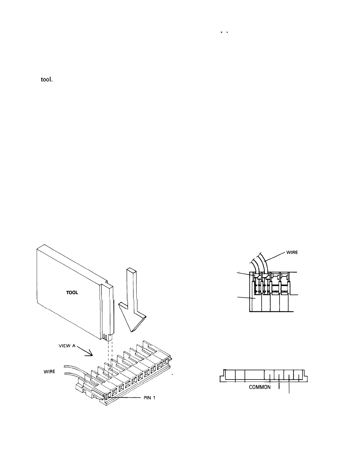
5. Note how the “teeth” on the special tool
supplied fit into the metal contacts in
the connector before actually inserting
any wires into the connector.
6. Press the wires firmly into the connector
as shown in Figure 3 using the special
tool.
NOTE: When pressing the wires firmly into the
connector, make sure the wire is positioned
all the way down into the slot and the
insulation crimp has been made around the
wire. It may be helpful to tap the tool with
an object such as a screwdriver handle.
7. Plug the mating connector into the fixed
connector.
ADJUSTING THE PAN LIMIT-STOPS
Wall Mount Version
1. Plug the control into an appropriate power
source.
2. Remove the pan limit-stops by pulling
down. The pan limit-stops are located
in the series of radial slots.
3. Press the joystick to pan to the desired
_
_
limit of right rotation.
An actuator lever extends down from the
pan-and-tilt head in the area between the head
and the wall mount, viewed from the rear of
the camera (Figure 4).
4. Press the limit-stop into the slot just to
the left of the actuator lever.
NOTE: Limit-stop selection is made in
IO-degree increments.
5. Press the joystick to pan to the desired
limit of left rotation.
6. Press the limit-stop into the slot just to
the right of the actuator lever.
7. Pan to each limit to check for exact trim.
8. Install the wall mount cover with the
three (3) screws provided.
Square Base Version
1. Plug the control into an appropriate power
source.
;::-.;i
TOOL
PUSH DOWN
LINE UP KEYS
WITH INSULATION
DISPLACEMENT TABS
CRIMP
CONNECTOR
LENS CONNECTOR DETAIL
87654321
I
I!l!l!lJ$
COMMON 1
IRIS
’
I
FOCUS
ZOOM
VIEW A
CONNECTOR SERIES
Figure 3
Wiring the Lens Connector
x573-492
 Loading...