7
Schematic Wiring Settings
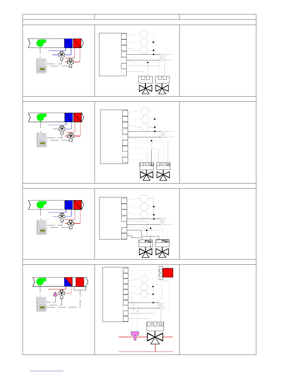
4 pipe system cooling and heating: VT7300C5x00(x) & VT7305C5x00(x) On / Off N.C. actuators
Mandatory
• Pipe no = 4 pipes
• CntrltTyp = On/Off
• Fan Menu = 0 (L-M-H)
• FL time = as per actuator
• SeqOpera = 4 Cool/Heat
4 pipe system cooling and heating: VT7300C5x00(x) & VT7305C5x00(x) Floating actuators
Mandatory
• Pipe no = 4 pipes
• CntrltTyp = Floating
• Fan Menu = 0 (L-M-H)
• FL time = as per actuator
• SeqOpera = 4 Cool/Heat
4 pipe system cooling and heating: VT7300F5x00(x) & VT7305F5x00(x) Analog actuators
Mandatory
• Pipe no = 4 pipes
• Fan Menu = 0 (L-M-H)
• RA/DA = as per actuator
• SeqOpera = 4 Cool/Heat
2 pipe system cooling or heating with reheat: VT7300C5x00(x) & VT7305C5x00(x) Floating actuator
Mandatory
• Pipe no = 2 pipes
• CntrltTyp = Floating
• Fan Menu = 0 (L-M-H)
• FL time = as per actuator
• SeqOpera = 2 Cool/Reheat
• UI3 = COS
24 V~ Com
24 V~ Hot
BO2 Close
Fan-L
Fan-M
Fan-H
High
Med
Low
24 Vac fan relays
CoolingHeating
BO4 Close
Normally Closed On/Off
Valve Cooling and Heating
Room Temperature
Control Thermostat
3 Speed fan
24 V~ Com
24 V~ Hot
BO1 Open
BO2 Close
Fan-L
Fan-M
Fan-H
High
Med
Low
24 Vac fan relays
Cooling
Heating
BO3 Open
BO4 Close
Modulating Floating
Valve Cooling and Heating
Room Temperature
Control Thermostat
3 Speed fan
24 V~ Com
24 V~ Hot
AO1
AO2
Fan-L
Fan-M
Fan-H
High
Med
Low
24 Vac fan relays
Cooling
Heating
0 to 10
Vdc
0 to 10
Vdc
Modulating Analog
Valve Cooling and Heating
Room Temperature
Control Thermostat
3 Speed fan
Optional supply water
temperature sensor
UI3 COS
24 V~ Com
24 V~ Hot
BO1 Open
BO2 Close
Fan-L
Fan-M
Fan-H
High
Med
Low
24 Vac fan relays
BO5
BO5
Modulating Floating
Valve Cooling and/or Heating
Room Temperature
Control Thermostat
3 Speed fan
Electric
Reheat