EasyManua.ls Logo

Vicruns VD530 Series - User Manual

Default Icon
232 pages
Print Icon
To Next Page IconTo Next Page
Loading...
Preface
Thank you for purchasing VD530 series inverters!
VD530 is a high-performance vector control inverter developed by VicRuns. Adopting advanced
vector control algorithm, it is widely used for asynchronous motor speed control. Through its
integrated EMC design and with optimized PWM control technique to meet users’ demand on
environmental requirement such as low-noise in application places and low EMI. It has perfect
anti-tripping control and good adaptive ability to bad power grid, temperature, humidity and dust, in
order to satisfy various sophisticated requirement under high precision drive applications, thus to
satisfy users expectation of higher reliability and stronger adaptability to environment of their
equipment, achieving industry specialization and personalized motor drive and control system
solution.
VD530 series high performance vector control inverter has following outstanding features:
1. Various control method
Supporting control method: SVC, FVC, V/F control.
2. Leading vector control algorithm
Optimized sensorless FVC control has better low speed stability, stronger low frequency load capacity,
supporting speed control and torque control.
3. Support multi-function I/O extension and multi-function MFI extension port
Multi-function I/O extension card, multi-function MFI extension port can connect related extension
function unit defined by manufacturer.
This manual provides the related issues: user installing and site wiring, quick debug, parameters
setting, failure diagnose and eliminate and daily maintenance and correlation matters. Please read
this manual to make sure you can install, use and maintain the inverter correctly, then play their
superior performance.
Please send this manual to the user or maintainer of this inverter, and properly kept.
Unpacking and Inspection:
Every inverter has been inspected rigorously before shipping.
Please confirm carefully when unpacking the packing carton:
● Check if any damage signs of the product and its package.
● Check if the model and inverter rated values on the nameplate are the same as stated on your order
and user manual.
● The box contains the inverter, manufacturer certificate, user manual.
If the product is damaged during transportation, or there is any omission or damage, please contact
our company or your local supplier immediately.
First time use suggests:
The users who use this product for the first time shall read this manual carefully. For any doubt on
certain functions and performances, please contact the technical support personnel of our company
for help, so as to use this product properly. With commitment to the constant improvement of the
inverter products, our company may change the information provided without additional notice.
VD530 series inverter is confirmed to below international standard, has passed the CE certification.
IEC/EN 61800-5-1: 2003 adjustable speed electric drive system safety regulation requirements;
IEC/EN 61800-3: 2004 adjustable speed electric drive system: part 3: product EMC standard and its
specific test method;
IEC/EN61000-2-1, 2-2, 3-2, 3-3, 4-2, 4-3, 4-4, 4-5, 4-6; EMC international and EU standard .

Table of Contents

Question and Answer IconNeed help?

Do you have a question about the Vicruns VD530 Series and is the answer not in the manual?

Summary

Preface

VD530 Series Features

Highlights key features of the VD530 series inverters.

Unpacking and Inspection

Instructions and checks for unpacking and inspecting the inverter upon arrival.

First Time Use Suggestions

Recommendations for initial setup and safe operation.

Chapter 1 Safety and Precautions

Safety Definitions and Levels

Defines DANGER and WARNING levels for safety precautions.

Installation Safety Precautions

Safety measures for before and during installation, including handling and wiring.

Chapter 1 Safety and Precautions

Wiring and Power-On Safety

Safety guidelines for wiring, connections, and pre-power-on checks.

Operation and Maintenance Safety

Safety measures during inverter operation and maintenance.

Chapter 1 Safety and Precautions

General Precautions for Motor and System

General advice on motor insulation, overheat protection, vibration, and resonance.

Chapter 1 Safety and Precautions

Operational and Environmental Considerations

Precautions for motor heating, output devices, voltage, altitude, DC bus, and disposal.

Adaptable Motor Guidelines

Specific advice on compatible motor types, cooling, and parameter settings for motors.

Chapter 2 Product Information

Designation Rules and Nameplate

Explains model designation rules and the importance of the nameplate.

Inverter Series Specifications

Lists technical data and specifications for different inverter models in the series.

Chapter 2 Product Information

Product Specifications Overview

Details technical specifications for power input, output, and main control functions.

Chapter 2 Product Information

Physical Appearance and Structure Diagram

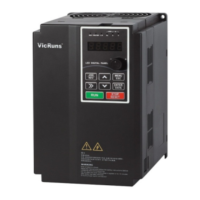
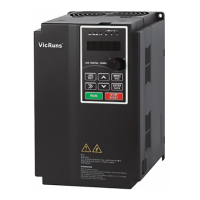
Illustrates the physical layout and main components of the inverter.

Chapter 2 Product Information

Appearance and Installation Dimensions

Provides schematic diagrams for physical dimensions and mounting dimensions of the inverter.

Chapter 2 Product Information

External Keyboard Dimensions

Diagrams and dimensions for the external keyboard and its holder.

Chapter 2 Product Information

Braking Unit Selection Guide

Guide to selecting braking resistors based on power and resistance values.

Chapter 2 Product Information

Routine Repair and Maintenance

Importance of routine maintenance to ensure inverter reliability and service life.

Chapter 2 Product Information

Maintenance Procedures

Daily checks, regular maintenance tasks, and replacement of wearable parts like fans and capacitors.

Chapter 2 Product Information

Warranty Information

Explains the product warranty period, conditions for free maintenance, and service charge policies.

Chapter 3 Mechanical and Electrical Installation

Installation Environment and Direction

Specifies environmental conditions and mounting orientation for proper inverter installation.

Chapter 3 Mechanical and Electrical Installation

Cover Plate and Keyboard Removal;Mounting

Instructions for removing and mounting the inverter's cover plate and keyboard.

Chapter 3 Mechanical and Electrical Installation

Inverter and External Electrical Parts Connection

Details on connecting external parts, main circuit terminals, and schematic diagrams.

Chapter 3 Mechanical and Electrical Installation

Standard Wiring Diagrams

Provides detailed wiring diagrams for single-phase and three-phase inverter configurations.

Chapter 3 Mechanical and Electrical Installation

Single-phase 220 V Inverter Wiring

Wiring diagram and precautions for the single-phase 220V inverter.

Chapter 3 Mechanical and Electrical Installation

Three-phase Inverter Wiring

Wiring diagrams and precautions for three-phase inverters based on power rating.

Chapter 3 Mechanical and Electrical Installation

Main Circuit Terminals and Instructions

Explains main circuit terminals, their functions, and connection instructions.

Chapter 3 Mechanical and Electrical Installation

Control Circuit Terminals and Functions

Details control circuit terminals, their functions, and power supply descriptions.

Chapter 3 Mechanical and Electrical Installation

Jumper Switchover Function Description

Explains how jumper settings configure terminal functions for analog and digital signals.

Chapter 4 Operation and Display

Operation and Display Interface Overview

Introduces the operation panel, its schematic, and keyboard button functions.

Chapter 4 Operation and Display

Function LED Indicators and Parameter Navigation

Explains LED indicators and methods for viewing/modifying function codes.

Chapter 4 Operation and Display

Motor Parameter Self-learning

Process and important points for performing motor parameter self-learning for optimal control.

Chapter 4 Operation and Display

Password and Parameter Lock Settings

Functionality for setting user passwords and locking parameters to prevent unauthorized changes.

Chapter 5 Function Parameter Table

F0 Basic Parameter Group

Lists basic parameters for Motor Control Mode, Running Command Source, and Frequency Source Selection.

Chapter 5 Function Parameter Table

F1 Start;Stop Control Group

Parameters for controlling inverter start, stop, DC braking, and speed tracking modes.

Chapter 5 Function Parameter Table

F2 Motor 1 Parameters

Configuration parameters for Motor 1, including type, nameplate data, and tuning options.

Chapter 5 Function Parameter Table

F3 Motor 1 Vector Control Parameters

Parameters for optimizing Motor 1's performance in vector control mode, covering speed and torque loops.

Chapter 5 Function Parameter Table

F4 Motor 1 V;F Control Parameters

Parameters for Motor 1 V/F control, including VF curve settings and torque boost.

Chapter 5 Function Parameter Table

F5 Input Terminal Group

Configuration of digital and analog input terminals for various functions like command modes and frequency sources.

Chapter 5 Function Parameter Table

F6 Output Terminal Function Group

Configuration of digital, relay, and HDO output terminals for status indication and alarms.

Chapter 5 Function Parameter Table

F7 Keyboard and Display Function Group

Parameters for customizing keyboard functions and LED display behavior for running and stop modes.

Chapter 5 Function Parameter Table

F8 Protection Parameters

Critical parameters for protecting the inverter and motor from overcurrent, overvoltage, and other faults.

Chapter 5 Function Parameter Table

F9 Fault Record and Setting Parameter Group

Parameters for recording fault history and configuring fault handling actions and automatic resets.

Chapter 5 Function Parameter Table

FA Process PID Parameter Group

Parameters for setting up and tuning the Process PID closed-loop control system.

Chapter 5 Function Parameter Table

Fb Enhance Function Group

Parameters for enhanced functions like jog control, acceleration/deceleration time switching, and frequency hopping.

Chapter 5 Function Parameter Table

FC Multi-reference and Simple PLC Parameters Group

Parameters for multi-reference settings and configuring the Simple PLC function.

Chapter 5 Function Parameter Table

Fd Communication Parameter Group

Parameters for setting up communication protocols like Modbus RTU for PC/PLC monitoring.

Chapter 5 Function Parameter Table

FF User Parameters Group

User management parameters including password, initialization, and custom function code settings.

Chapter 5 Function Parameter Table

A0 Motor 1 Torque Control Parameter Group

Parameters for controlling Motor 1's torque, including mode selection, setting sources, and compensation.

Chapter 5 Function Parameter Table

A2 Motor 2 Parameters

Configuration parameters for Motor 2, including type, nameplate data, and tuning options.

Chapter 5 Function Parameter Table

A3 Motor 2 Vector Control Parameters

Parameters for vector control of Motor 2, covering speed loop and torque control adjustments.

Chapter 5 Function Parameter Table

A4 Motor 2 V;F Control Parameters

Parameters for Motor 2 V/F control, including VF curve settings and oscillation suppression.

Chapter 5 Function Parameter Table

b0 User Customize Function Code

Allows users to map frequently used parameters to custom codes for quick access.

Chapter 5 Function Parameter Table

b1 Virtual IO Parameter Group

Configuration of virtual digital input (VDI) and output (VDO) terminals for flexible logic control.

Chapter 5 Function Parameter Table

b2 AI Curve Setting

Defines custom input curves for analog signals, allowing non-linear input-output relationships.

Chapter 5 Function Parameter Table

b3 AIAO Correction Parameter Group

Calibration parameters for analog inputs and outputs to correct for zero bias and gain errors.

Chapter 5 Function Parameter Table

C0 Special Group of Tension Control

Parameters specific to tension control applications, including coil diameter calculation and material settings.

Chapter 5 Function Parameter Table

U0 Basic Monitoring Parameters

Displays real-time inverter status and monitored values like frequency, voltage, and current.

Chapter 6 Parameter Description

F0 Basic Function

Explains essential parameters like Motor Control Mode, Running Command Source, and Frequency Source Selection.

Chapter 6 Parameter Description

F1 Start;Stop Control Group

Parameters for controlling inverter start, stop, DC braking, and speed tracking modes.

Chapter 6 Parameter Description

F2 Motor 1 Parameters

Configuration parameters for Motor 1, including type, nameplate data, and tuning options.

Chapter 6 Parameter Description

F3 Motor 1 Vector Control Parameters

Parameters for optimizing Motor 1's performance in vector control mode, covering speed and torque loops.

Chapter 6 Parameter Description

F4 Motor 1 V;F Control Parameters

Parameters for Motor 1 V/F control, including VF curve settings and torque boost.

Chapter 6 Parameter Description

F5 Input Terminal Group

Configuration of digital and analog input terminals for various functions like command modes and frequency sources.

Chapter 6 Parameter Description

F6 Output Terminal Function Group

Configuration of digital, relay, and HDO output terminals for status indication and alarms.

Chapter 6 Parameter Description

F7 Keyboard and Display Function Group

Parameters for customizing keyboard functions and LED display behavior for running and stop modes.

Chapter 6 Parameter Description

F8 Protection Parameters

Critical parameters for protecting the inverter and motor from overcurrent, overvoltage, and other faults.

Chapter 6 Parameter Description

F9 Fault Record and Setting Parameter Group

Parameters for recording fault history and configuring fault handling actions and automatic resets.

Chapter 6 Parameter Description

FA Process PID Parameter Group

Parameters for setting up and tuning the Process PID closed-loop control system.

Chapter 6 Parameter Description

Fb Enhance Function Group

Parameters for enhanced functions like jog control, acceleration/deceleration time switching, and frequency hopping.

Chapter 8 Fault Shooting and Solutions

Fault Alarm and Countermeasures

Lists common inverter error codes, possible causes, and corresponding solutions for troubleshooting.

Chapter 8 Fault Shooting and Solutions

Common Faults and Solutions

Addresses common faults like no display, power supply issues, and motor not moving, providing troubleshooting steps.

Chapter 9 Communication Protocol

Modbus Communication Overview

Introduces the Modbus-RTU protocol, application methods, and bus structure.

Communication Frame Structure and Data Description

Details the Modbus RTU frame structure, command codes, and data formats.

Appendix A Multi-function I;O Extension Card

Multi-function I;O Extension Card Overview

Introduces the multi-function I/O extension card, its terminals, and installation diagram.

Appendix A Multi-function I;O Extension Card

Installation Considerations for Extension Card

Notes on correctly installing the multi-function I/O extension card onto the main control board.

Appendix A Multi-function I;O Extension Card

Socket and Jumper Function Descriptions

Details the function of sockets and jumper settings for configuring the extension card.

Appendix B Incremental PG Card

Introduction to PG Card

Introduces the incremental PG card for closed-loop vector control and describes its terminals.

Appendix B Incremental PG Card

PG Card Debugging Procedures

Steps for debugging the PG card, including wiring, parameter setting, and verification.

Warranty Agreement

Warranty Terms and Exclusions

Outlines the 18-month warranty period, conditions for free maintenance, and exclusions.

Product Warranty Card

Vicruns VD530 Series Specifications

General IconGeneral
Cooling MethodForced Air Cooling
IP RatingIP20
Output Voltage0 - Input Voltage
Power Range0.75kW - 630kW
Protection FeaturesOvervoltage, Undervoltage, Overcurrent, Overtemperature, Short Circuit
Communication InterfaceRS485, Modbus
Operating Temperature-10°C~+40°C
Storage Temperature-20°C~+60°C
Humidity5%~95% (Non-condensing)
Altitude≤1000m (Above 1000m derating required)
Control MethodVector Control/Scalar Control

Related product manuals