HYBRID EMITTER REQUIREMENTS – PLENUM AREA
1. Hybrid emitters installed in the plenum shall be located in a sidewall configuration along the back wall of the plenum.
2. Refer to Section II of the I-VORTEX.IOM for hybrid emitter material, connection detail, nitrogen and water flow, and pressure requirements.
3. Hybrid emitters shall be placed to avoid any obstructions that can block discharge.
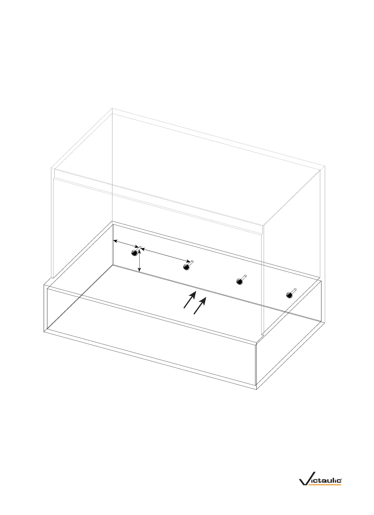
4. Hybrid emitters shall be placed, as shown in the drawing below.
• Maximum protected volume of a single hybrid emitter is 32.5 ft
3
/0.92 m
3
.
• Maximum protected height of each hybrid emitter is 24 inches/610 mm.
• Maximum protected depth of each hybrid emitter is 90 inches/2286 mm in the direction of discharge.
• Hybrid emitters are to be installed mid-height of the space, projected horizontally.
• Maximum hybrid emitter spacing is 24 inches/610 mm.
Airow
8.5 inches/
216 mm
Maximum
24.0 inches/
610 mm
Maximum
12-inch/
304.8-mm
Minimum
Clearance
UNVENTILATED AUXILIARY COMPARTMENTS
1. Unventilated auxiliary compartments with minimal leakage may be protected by hybrid emitters that discharge nitrogen only in pendent or sidewall
configurations.
2. When water is not used, the water connection on the hybrid emitter shall be plugged.
3. Use one hybrid emitter per 65 ft
3
/1.8 m
3
of compartment volume.
4. Hybrid emitters shall be placed to avoid any obstructions that can block discharge.
VDM-VORTEX.04_4 REV_A
 Loading...