HYBRID EMITTER REQUIREMENTS – WORKING SURFACE
1. Hybrid emitters installed over the working surface shall be mounted in a pendent configuration.
2. Refer to Section II of the I-VORTEX.IOM for hybrid emitter material, connection detail, nitrogen and water flow, and pressure requirements.
3. Hybrid emitters shall be placed to avoid any obstructions that can block discharge.
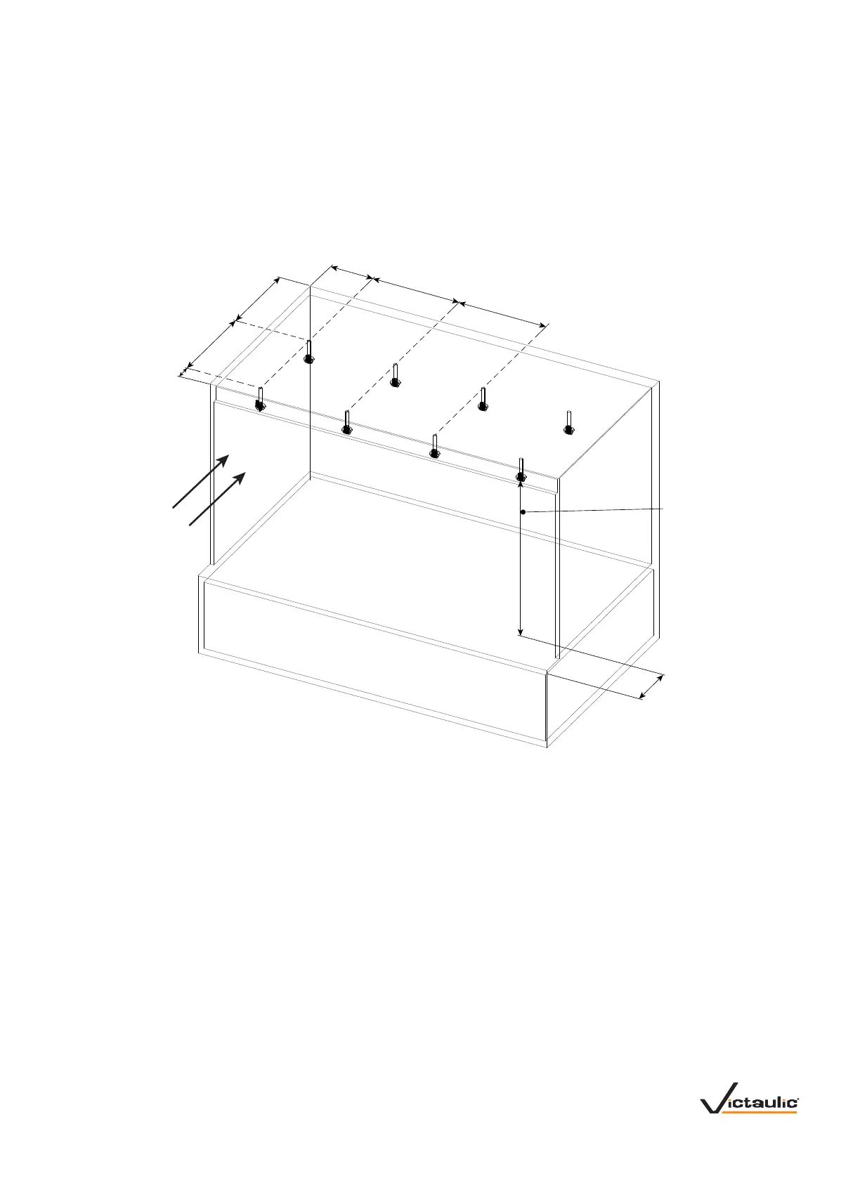
4. Hybrid emitters shall be placed, as shown in the drawing below.
• Each hybrid emitter covers a maximum area of 24 x 30 inches/610 x 762 mm (5 ft
2
/0.5 m
2
).
• Hybrid emitters shall be a vertical distance of 36 – 55 inches/914 – 1397 mm from the working surface.
• Hybrid emitter location shall be a maximum of 8 ½ inches/216 mm from the sides of the working surface.
• Hybrid emitter location shall be a maximum of 23 ½ inches/597 mm from the back wall of the working surface.
• Hybrid emitter location shall be a maximum of 16 inches/406 mm from the front edge of the working surface.
16.0 inches/
406 mm
Maximum
Height
36.0 inches/
914 mm Minimum
53.0 inches/
1346 mm Maximum
Airow
216 mm
Maximum
24.0 inches/
610 mm
Maximum
24.0 inches/
610 mm
Maximum
4.5 inches/
114 mm
Maximum
30.0 inches/
762 mm
Maximum
23.5 inches/
597 mm
Maximum
VDM-VORTEX.04_3REV_A
 Loading...