SET-UP AND SAFE OPERATING PROCEDURES
4-21
0056-0114
WARNING
There must always be two O-rings on the cone end. The absence or damage of either
of these O-rings will allow premixing and leaks of oxygen and fuel gases. This can lead
to a sustained backfire within the torch handle or cutting attachment.
The center orifice of the cone end, like the center port of the torch handle head, allows the passage
of the oxygen supply. The orifices around the oxygen port allow the fuel gas to travel to the mixing
chamber in the lower tube of the cutting attachment.
Preheat Oxygen Control Valve
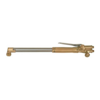
When the cutting attachment is connected to the torch handle, the preheat oxygen control valve on the
cutting attachment controls the preheat oxygen supply from the regulator. To function in this manner,
the oxygen valve on the torch handle must be opened completely. The preheat oxygen supply is then
increased or decreased by opening or closing the cutting attachment control valve. The fuel supply
is controlled by the fuel valve on the torch handle.
Mixing Chamber Tube
Fuel and oxygen are mixed to produce the desired preheating flame. To accomplish the necessary
mixing of gases, oxygen and fuel are fed into a mixing chamber located in the forward portion of the
cutting attachment mixing chamber tube. Oxygen is directed to the mixer through the inner oxygen
tube. The fuel gas is drawn from the exterior cavity of the attachment’s lower tube around the mixer.
Mixed gases then flow through the preheat orifices of the cutting attachment head and into the
preheat orifices of the cutting tip.
Cutting Oxygen Lever and Tube
The cutting oxygen lever is located above the body of the cutting attachment. When the oxygen
control valve on the torch handle is open, depressing the lever allows cutting oxygen to flow through
the upper tube of the cutting attachment and the center port of the cutting attachment head. The
upper oxygen tube is designed to allow the maximum supply of oxygen to the cutting operation and
to provide structural strength by the utilization of high strength tubing.
Cutting Attachment Head
The cutting attachment head is designed to allow the cutting oxygen and the mixed preheat gas to
stay separated during the cutting operation. The exterior of the torch head is threaded and the interior
of the head is tapered. The internal taper of the head is stepped allowing the preheat gases to feed
the cutting tip through the exterior orifices and the cutting oxygen can travel uninterrupted through
the center port of the tip to the heated base metal (see Figure 6, page 23). The exterior threads on
the head allow a tip nut to compress a cutting tip into the tapered head. This creates a firm gas-tight
metal-to-metal seat.
Cutting Tip
Cutting tips are available in a wide variety of configurations and sizes. Cutting tips keep the preheat
gas mixture and cutting oxygen stream separated and provide flame characteristics needed for a
particular cutting application. Tips are sized according to the thickness of metal they can cut. For
instance, a number 000 tip is designed to cut metal 1/16” to 1/8” in thickness, and a number 00 tip
will cut metal 1/8” to 1/4” in thickness. For further information on tip sizes and selections, refer to
the charts located on pages 50-55.
Oxy-fuel Apparatus


 To Next Page
 Loading...