EasyManua.ls Logo

Victor VC60D+ - User Manual

Victor VC60D+
2 pages
Print Icon
To Next Page IconTo Next Page
Loading...
INSULATION TESTER INSTUCTION MANUAL
1. Introduction
The digital megohmmeter uses the DC-excited transducer to convert DC 12V to DC high voltage 1000V/2500V. The main
amplifier tests the insulation voltage by the current ratio measurement of traditional megger. The input terminal uses micro-
current to test anti-interference circuit and the output terminal adopts the division function of double integrating digital
voltmeter to process the data conversion. It is characteristic of strong loading capacity, high anti-interference of electric field,
portable operation, wide range, backlight display and so on. It could also be used to test commercial electric power. With its
stable performance and high grade appearance, it is widely used to test the insulated voltage resistance for electrical equipment,
instrumentation, cables and so on.
2. Appearance Description
1.2.3.4. Voltage Selection Switch (It includes
AC750V/200M/ 2GΩ/20GΩ
)
5. Voltage Selection Switch (
1000V/2500V
) (except AC750V)
6. Power Switch: Self-locking power switch (POWER).
7. High voltage indication: LED display.
8. Test Switch
9. LCD display: display the measuring value and unit symbol.
10. Instrument mode
11. L: jack for circuit under test.
12. G: Protection jack. When the object under test is requested to add
the protection ring to eliminate leakage effects, the electrode wire
of protection ring should be connected to "G" jack.
13. ACV: Input end for AC voltage measurement.
14. E: Jack for object under test.
15. Power adapter jack
).
3. Technical Features
3.1. General Features
(1) Display: 84.8×59.8mm LCD display. The max display “1999”.
(2) Over range indication: the MSD shows "1" when it is over ranged.
(3) Alarm function: the meter will alarm automatically when the tested resistance is below the lower range and the reading is
invalid.
(4) Power supply: #5 batteries LR6 (1.5) ×8.
(5) Low battery indication:
displays
(6) Operation environment: temperature 0
40
30% R.H- 85% R.H
(7) Weight: Approx. 630g (including batteries)
3.2 Technical index
Basic function Range Basic accuracy
Output Voltage 1000V/2500V ±10%
Short-circuit current <4mA
Insulated Resistance 1000V 200MΩ:6.0-199.9MΩ ±(5%±5 digit
2GΩ:0.06-1.999GΩ ±(5%±5 digit
20GΩ:0.6-19.99GΩ ±(5%±5 digit
Insulated Resistance 2500V 200MΩ:5-199.9MΩ ±(5%±5 digit
2GΩ:0.05-1.999GΩ ±(5%±5 digit
20GΩ:0.5-19.99GΩ ±(5%±5 digit
200GΩ:5.0-199.9GΩ ±(5%±5 digit
Voltage Measurement AC750V ±
1% +6 digit
Jack Position Insulated Resistance: L
E AC750V: ACV G
ACV750V input impedance: 1MΩ.
15
Question and Answer IconNeed help?

Do you have a question about the Victor VC60D+ and is the answer not in the manual?

Summary

Introduction to Insulation Tester

Insulation Tester Appearance and Components

Voltage and Range Selection

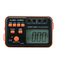
Switches for selecting test voltage (1000V/2500V) and measurement ranges.

Controls and Display

Includes Power, Test Switch, LCD display, and indicators for operation.

Input Terminals and Jacks

Designates L, G, E, and ACV jacks for connecting the circuit under test.

Technical Features and Specifications

General Features Overview

Details display, over range, alarm, power, low battery, and environmental specs.

Technical Index and Accuracy

Lists output voltage, current, resistance ranges, accuracy, and voltage measurement specs.

Operating Instructions

Preparation and Setup

Instructions for battery installation and initial power-on.

Test Execution Procedure

Steps for selecting voltage/range and performing the insulation test.

Interpreting Measurement Results

Guidance on handling over-range indications and ensuring stable readings.

Safety Precautions

High Voltage and Electrical Safety

Warnings about high voltage output, grounding, and discharge procedures.

Measurement and Environmental Guidelines

Checks for voltage, battery status, avoiding interference, and environmental conditions.

Instrument Components List

Overview

This document describes an Insulation Tester, a digital megohmmeter designed for measuring insulated voltage resistance in electrical equipment, instrumentation, and cables.

Function Description

The device operates by converting a DC 12V input into high DC voltages of 1000V or 2500V using a DC-excited transducer. It then tests insulation voltage through a current ratio measurement method, similar to traditional meggers. The input terminal employs a micro-current anti-interference circuit, and the output terminal utilizes a double integrating digital voltmeter for data conversion. It can also be used for testing commercial electric power.

Important Technical Specifications

General Features:

  • Display: 84.8×59.8mm LCD, with a maximum display of "1999".
  • Over Range Indication: MSD shows "1".
  • Alarm Function: Alarms automatically when tested resistance falls below the lower range, indicating an invalid reading.
  • Power Supply: 8 x #5 LR6 (1.5V) batteries.
  • Low Battery Indication: "+" symbol.
  • Operation Environment: Temperature 0~40℃, 30% R.H- 85% R.H.
  • Weight: Approximately 630g (including batteries).

Technical Index:

  • Output Voltage: 1000V/2500V.
  • Short-circuit current: <4mA.
  • Insulated Resistance (1000V):
    • 200MΩ: 6.0-199.9MΩ (±(5%±5 digit))
    • 2GΩ: 0.06-1.999GΩ (±(5%±5 digit))
    • 20GΩ: 0.6-19.99GΩ (±(5%±5 digit))
  • Insulated Resistance (2500V):
    • 200MΩ: 5-199.9MΩ (±(5%±5 digit))
    • 2GΩ: 0.05-1.999GΩ (±(5%±5 digit))
    • 20GΩ: 0.5-19.99GΩ (±(5%±5 digit))
    • 200GΩ: 5.0-199.9GΩ (±(5%±5 digit))
  • Voltage Measurement: AC750V (± (1% +6 digit)).
  • ACV750V Frequency Response: (50~200) Hz.
  • ACV750V Input Impedance: 1MΩ.

Usage Features

Appearance Description: The device features several switches and jacks for operation:

  • Voltage Selection Switches (1, 2, 3, 4): For AC750V/200MΩ/2GΩ/20GΩ.
  • Voltage Selection Switch (5): For 1000V/2500V (except AC750V).
  • Power Switch (6): Self-locking "POWER" button.
  • High Voltage Indication (7): LED display.
  • Test Switch (8).
  • LCD Display (9): Shows measuring value and unit symbol.
  • Instrument Mode (10).
  • L Jack (11): For the circuit under test.
  • G Protection Jack (12): Connects to the protection ring to eliminate leakage effects from the tested object.
  • ACV Input End (13): For AC voltage measurement.
  • E Jack (14): Ground terminal for the object under test (e.g., metal shell, transformer core, cable shield, earth).
  • Power Adapter Jack (15): (+-).

Operating Instructions:

  1. Battery Installation: Open the back cover and insert 8 x #5 batteries, ensuring correct polarity.
  2. Power On: Press the "POWER" switch.
  3. Voltage Selection: Select the desired test voltage (1000V/2500V) and range.
  4. Cable Connection:
    • Connect the "L" terminal to the circuit under test using a special cable.
    • Connect the "G" terminal to the protection ring if needed to eliminate leakage.
    • Connect the "E" terminal to the ground of the tested object.
  5. Start Test: Press the test switch. Readings are available once the display stabilizes. Release the switch after the reading is complete.
  6. Over Range: If the MSD displays "1", select a higher range.

Maintenance Features

Safety Precautions:

  • High Voltage Warning: The "L" terminal is high voltage output. The "E" terminal must be connected to ground.
  • Discharge Procedure: The tested object must be removed from the power network and artificially discharged before connecting or disconnecting to ensure safety.
  • Avoid Sparking: Minimize high voltage sparking during measurement to prevent instrument damage.
  • Voltage Verification: Always check that the selected testing voltage matches the voltage displayed on the LCD or panel.
  • Battery Replacement: Replace batteries when the "+" symbol indicates low battery power.
  • Stable Readings: If readings are unstable due to environmental interference or unstable insulation, connect the "G" terminal to the shielded side of the tested object.
  • Environmental Protection: Keep the instrument away from humid places and direct sunlight to protect the LCD monitor.
  • Cable Integrity: Use only the provided silicone rubber cable line for safety. Do not replace the measuring line randomly.
  • External Adapter Use: When using an external adapter, the battery power is automatically disconnected. Do not charge batteries at this time. Ensure the correct power supply mode (+-) is selected.

Whole Components of the Instrument:

  • Megohmmeter: One
  • Measuring cable: One
  • Silicone rubber cable: One
  • #5 batteries (1.5v)×8: Eight
  • Instruction Manual: One

Victor VC60D+ Specifications

General IconGeneral
BrandVictor
ModelVC60D+
CategoryTest Equipment
LanguageEnglish

Related product manuals