Do you have a question about the Victory V40 The Duchess and is the answer not in the manual?
Essential safety guidelines for operating the amplifier, including handling and environment.
Conditions requiring professional service and the importance of using correct replacement parts.
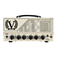
Details on the input jack and volume control for setting sensitivity and overdrive levels.
Explanation of the Voice I/II switch, Treble, Middle, Bass, and Mid Kick controls.
How to use the Reverb control and Master Volume, plus the Reverb ON/OFF toggle switch.
Information on the Master Volume and the HIGH-STANDBY-LOW power mode selection switch.
Overview of rear panel features including fuses, speaker outputs, and serial connection points.
Instructions for selecting the correct mains voltage, with crucial safety considerations.
Details on mains and HT fuses, their ratings, and procedures for safe replacement.
Connecting speaker cabinets to the 8 Ohm and 16 Ohm output jacks for optimal performance.
Utilizing the push switch for FX Loop bypass and Reverb ON/OFF control.
Connecting and using external effects units via the SEND and RETURN loop sockets.
Locating and connecting the single-way footswitch for Reverb ON/OFF control.
Activating and understanding the low-power Class A mode via the rear panel switch.
Detailed steps for re-biasing output valves after replacement, including safety.
Measuring and adjusting the BIAS voltage using test points and a multimeter.
Key specifications including dimensions, weight, and output power ratings.
Information on the 5-year limited warranty, valve warranty, and how to get support.
| Brand | Victory |
|---|---|
| Model | V40 The Duchess |
| Category | Music Equipment |
| Language | English |