Do you have a question about the Victron energy Smart BatteryProtect 12/24V and is the answer not in the manual?
| Maximum Continuous Load Current | 65 A |
|---|---|
| Protection Category | IP43 |
| Alarm Output | Yes |
| Programmable | Yes |
| Nominal Voltage | 12/24V |
| Operating Temperature Range | -40°C to +50°C |
| Input Voltage Range | 6 to 35 V DC |
| Protection | Over voltage, over temperature |
| Communication | Bluetooth |
| Compatibility | VictronConnect |
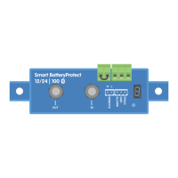
Essential installation guidelines: ventilation, cable size, fuse, orientation, short circuit handling, GND connection, and voltage detection.
Crucial warning against connecting inverters/chargers directly to DC inputs due to reverse current damage. Use remote port instead.
Shows basic wiring with a wire loop or switch for remote on/off, explaining load disconnection logic.
Illustrates wiring a simple switch to the remote terminals for system on/off control.
Describes wiring for Li-ion systems with external BMS, using ATD/ATC outputs for load control, requiring Li-ion mode.
Explains wiring using a BMS's load/charge disconnect outputs to the SBP's H input for controlled disconnection.
Details using multiple SBPs for simultaneous control of chargers and loads, managed by BMS signals.
Explains how to connect external devices like LEDs, buzzers, or relays to the SBP's alarm output.
Describes three modes (Buzzer/LED, Relay, Li-ion) and their effects on alarm output and BMS control.
Step-by-step guide to configure the SBP using the VictronConnect app via Bluetooth.
Method for programming the SBP using the PROG pin and GND pin, often with a push button.
Lists voltage settings and operation modes corresponding to 7-segment display codes for programming.
Explains how the 7-segment display's decimal point indicates the SBP's operational status.
Details SBP behavior when controlled remotely or when a short circuit is detected.
Lists possible error/warning codes displayed by the SBP and their meanings or causes.
Detailed specifications for SBP models (SBP-65, SBP-100, SBP-220) covering electrical and physical parameters.
Provides a detailed list of error and warning codes with their descriptions and recommended actions for troubleshooting.