EasyManua.ls Logo

Victron energy BatteryProtect - User Manual

Victron energy BatteryProtect
16 pages
Print Icon
To Next Page IconTo Next Page
Loading...
BatteryProtect 12/24V
12/24V - 65A | 12/24V - 100A | 12/24V - 220A
rev 04 - 11/2023
This manual is also available in HTML5.
ENGLISH
Question and Answer IconNeed help?

Do you have a question about the Victron energy BatteryProtect and is the answer not in the manual?

Summary

Introduction

Features

Installation and wiring examples

Precautions and installation notes

Essential guidelines for safe and correct installation of the BatteryProtect unit.

Warning connecting inverters;chargers

Critical advice on connecting inverters and inverter/chargers to avoid damage.

BatteryProtect in a simple system

Wiring example for basic system setup with the BatteryProtect.

BatteryProtect remote on;off switch

Wiring example demonstrating remote system control using a switch.

BatteryProtect in lithium battery system with BMS

Wiring configuration for lithium batteries managed by an external BMS.

BatteryProtect lithium system with load disconnect

Wiring for lithium systems with BMS controlling load disconnect via BatteryProtect.

Two BatteryProtects for load and charger control

Example of using multiple BatteryProtects for managing both loads and chargers.

Battery Protect Alarm output wiring

Guidance on connecting external devices like LEDs or buzzers to the alarm output.

Operation and programming

Operation modes

Description of the three available operating modes for the BatteryProtect.

Programming via PROG pin method

Detailed procedure for programming the BatteryProtect using the PROG pin.

Programming table

Reference table for voltage shutdown and restart settings in different modes.

Status indicator

Explanation of the 7-segment display for status and error indication.

Remote control and short circuit behavior

How the BatteryProtect responds to remote control signals and short circuits.

Error & Warning modes

List and explanation of error codes (E1-E4) and warning indicators.

Technical specifications

Technical Specifications

Detailed specifications including current, voltage, weight, and dimensions.

Appendix

Error and Warning codes

Comprehensive list of error codes with solutions and troubleshooting advice.

Overview

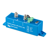
The Victron Energy BatteryProtect is a crucial device designed to safeguard batteries from excessive discharge, which can lead to damage, or from having insufficient power to crank an engine. It also offers an alternative method to disable chargers that lack a remote on/off port, thereby protecting against over-voltage. This uni-directional device manages current flow in one direction only, either to a load or from a charger, but not simultaneously. Current is strictly intended to flow from the IN terminal to the OUT terminal.

Function Description

The primary function of the BatteryProtect is to disconnect the battery from non-essential loads before it reaches a critically low state of charge. This prevents deep discharge, which can significantly shorten battery lifespan. It also acts as an over-voltage protection device, disconnecting loads if the DC voltage exceeds predefined thresholds (e.g., 16.3V for a 12V system or 32.6V for a 24V system) to protect sensitive electronics.

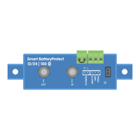
For systems utilizing lithium batteries with external Battery Management Systems (BMS), the BatteryProtect offers a specialized "Li-ion mode." In this mode, it can be controlled by the BMS's load disconnect output, providing immediate disconnection of the load if the BMS detects an under-voltage condition in the battery cells. This ensures optimal protection for lithium battery chemistries.

The device features an ultra-low current consumption of 1.5mA when active and 0.6mA when off or in low voltage shutdown. This is particularly beneficial for Li-ion batteries, especially after a low voltage shutdown, as it minimizes parasitic drain. The BatteryProtect is also ignition-proof, utilizing MOSFET switches instead of relays, which eliminates the risk of sparks.

Usage Features

The BatteryProtect offers several features that enhance its usability and integration into various power systems:

  • 12/24V Auto Ranging: The device automatically detects the system voltage (12V or 24V) during initial power-up. Once detected, this voltage is stored, and further automatic detection is disabled. This simplifies installation and ensures compatibility with common battery voltages.
  • Programmable Operating Modes: The BatteryProtect has three distinct operating modes that can be selected via a programming procedure:
    • Mode A (Buzzer or LED mode - default): In this mode, a continuous alarm sounds after 12 seconds if under-voltage is detected. The load is disconnected after 90 seconds, and the alarm stops. For over-voltage, the load is immediately disconnected, and an intermittent alarm persists until the over-voltage is resolved.
    • Mode B (Relay mode): In under-voltage scenarios, a relay engages after 12 seconds. The load is disconnected after 90 seconds, and the relay disengages. Over-voltage leads to immediate load disconnection, but the alarm output remains inactive.
    • Mode C (Li-ion mode): Specifically designed for lithium batteries with external BMS (or BMS with load/charge disconnect outputs). In this mode, the BatteryProtect responds directly to the BMS's load or charge disconnect signal. Under-voltage thresholds and the alarm output of the BatteryProtect are inactive, as protection is managed by the BMS.
  • Delayed Alarm Output: The alarm output activates only if the battery voltage remains below the preset disconnect level for more than 12 seconds. This prevents false alarms triggered by transient voltage drops, such as those caused by engine starting.
  • Delayed Load Disconnect and Reconnect: The device incorporates delays for both load disconnection and reconnection. This allows users to respond to warnings (e.g., by reducing load or starting a generator/charger) before the load is completely switched off. In Li-ion mode, a 30-second delay is observed after the remote input becomes free-floating, and a 3-minute delay for frequent switching, ensuring system stability.
  • Remote On/Off Switch Capability: A remote on/off switch can be connected to the dedicated 2-pin remote terminal. This allows for convenient remote control of the system, enabling users to turn the system on or off without direct access to the BatteryProtect. Alternatively, the REMOTE terminal can be switched high (to battery positive) to activate the device.
  • Alarm Output for External Indicators: The alarm output terminal can be connected to a buzzer, LED, or relay, providing visual or audible indications of system status or warnings. The maximum load on the alarm output is 50mA, and it is short-circuit proof.
  • Short Circuit Protection: The BatteryProtect includes short circuit protection, which activates in the event of a short circuit, overload, or excessive inrush current. If a short circuit is detected, the device will attempt to reconnect the load every 5 seconds. After two attempts, it will display an E1 error.

Maintenance Features

While the BatteryProtect is a robust and low-maintenance device, certain considerations contribute to its longevity and reliable operation:

  • Proper Installation: Installing the BatteryProtect in a well-ventilated area, preferably close to the battery (within 50 cm), is crucial. This helps dissipate heat and ensures optimal performance. However, it should not be installed directly above the battery due to potential corrosive gases.
  • Correct Cable Sizing: Using appropriately sized and adequately protected cables between the battery and the BatteryProtect is essential. Undersized or long cables can lead to voltage drops, potentially triggering short circuit alarms or unexpected shutdowns.
  • Fuse Protection: A properly sized fuse, in accordance with local regulations, must be installed in the cable between the battery and the BatteryProtect to protect the system from overcurrents.
  • Correct Orientation: The device must be installed with the correct orientation, ensuring current flows from the IN (battery) terminal to the OUT (load) terminal. Reverse currents are strictly forbidden and can damage the device.
  • Dedicated GND Connection: The supplied 1.5mm² wire for the GND connection should be connected directly to the battery negative terminal (or vehicle chassis). No other equipment should be connected to this wire, and it should be protected with a 300mA fuse.
  • Programming for System Changes: If the BatteryProtect is reused in a different installation or if the system voltage needs to be reset, the programming procedure can be initiated to redetect the system voltage or select a different operating mode.
  • Error and Warning Codes: The 7-segment display provides error and warning codes (E1, E2, E3, E4) that indicate specific issues such as short circuits, over-temperature, under-voltage, and over-voltage. Understanding these codes allows for efficient troubleshooting and maintenance. After 5 minutes, error codes are no longer displayed to reduce current consumption, but the underlying issue persists until resolved.
  • Environmental Considerations: Avoiding installation in locations exposed to high temperatures or radiant heat is recommended. If necessary, relocating the BatteryProtect to a cooler position or providing additional active cooling can prevent over-temperature issues.

Victron energy BatteryProtect Specifications

General IconGeneral
ModelBatteryProtect
ManufacturerVictron Energy
CategoryPower distribution unit
Alarm OutputYes
Remote ControlYes
ProgrammableYes
Continuous Current65A, 100A, 220A
Peak CurrentVaries by model
Battery Low Voltage DisconnectProgrammable
Battery Low Voltage ReconnectProgrammable
Operating Temperature-40°C to +50°C
ProtectionOverload, short circuit, reverse polarity
WeightVaries by model
DimensionsVaries by model

Related product manuals