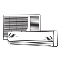
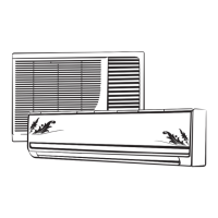
NAME OF PARTS
( ).
Emergency Operation switch
3.EMERGENCY OPERATION SWITCH
In case thebatteries in the remote controller areworn out, or remote controller is at fault, use
Emergency operation switch
Cooling only type
Every time the switch is pressed,it changes in sequence of COOL STOP.
The following table shows the condition of set temperature, fan speed and deflector during
emergency operation.
4.HORIZONTAL LOUVER BLADE
Hold the knob and move the deflector to change right/left airflow direction. Be careful not to adjust
the deflector during operation as the fan is rotating at a high speed and may pinch your fingers.
Mode
Set temperature
Deflector
Fan speed
SwingHigh
Cooling
24
C
5
22
The places of e different models maybe different, but all of the
e ¡ °¡ ¡ ¡ ¡ ¡ ±
mergency operation switch of
mergency operation switches are showed by the icon .
POWER
COOL
WARM
SLEEP
TIMER
COOL MODE
indicator lamp
Sleep indicator
lamp
Timer indicator
lamp
Run indicator
lamp
HEAT PUMP MODE
indicator lamp
or
or
CUSTOMER COPY
Name of Customer:
Model:
Serial Number:
Date of Purchase / Date of Installation:
Installation Done By:
Name of Service Center:
Commissioning:
10. Run the machine for 30minutes
& check for the following.
a) Vibration / abnormal noise observation.
If yes provide detail.
i) Checked for earthing with the unit_______V
(Voltmeter reading must be less than 3V)
Ii) Supply between L & E - 230 10% ______V±
E
V
L
N
iii) Supply between L & E - 230 10% ______V±
Output: ______V
c) Stabilizer Installed Yes/No If Yes Make:
d) Current Drawin by the machine _____A Specify under test run.
e) Temperature Reading
b) Electrical supply input Volts________V
If more than 3V,
please consult
electrician for
proper earthing
to the unit.
Return Temperature
C
Supply Temperature
C
Difference C
Difference should be
more than 12 Degree C
Has the Indoor Unit been placed with slope towards
drain end. If yes, mention angle of slope.
Note: Water to be poured in drain Pan & proper
draining from drain pipe to be checked.
Yes/No
Yes/No
Customer Remarks / Signature:
Service center stamp
Installer Sign
Room Dimensions:
Yes/No
Yes/No
Yes/No
Yes/No
Yes/No
Yes/No
Yes/No
______Gms
Yes/No
Yes/No
Length-
Width-
Height-
NOrth/South/East/West
8. Installation of the Unit as per below distance spec.
9. All flarinng has to be done as per the Installation Manual
Address:
Contact Number:
Installation
1.Is the Capacity of the machine
suitable for the room in which
machine is installed
2. Is the strength of installation enough.
Is the machine installed securely on installation plate
3. Direction of condenser of
machine is towards
4. If the direction of the condenser is towards south
or west proper shade provided to the machine
5. Specify piping length
Horizontal & Vertical Distance
between IDU & ODU
H _____ m
_____ m
V _____ m
6. Has the IDU been placed below ODU
If yes, have U traps been provided at
every 5m.
7. Has gas charging been done
for extra length of Piping
Grade
Clearance (cm)
7K-28K
A
B
30K- 38K
10
30
5
12
More than 70cm
More than 10cm
More than 60cm
More than 10cm
More than 60cm
More than “A”
More than “B”
More than “B”
More than 2.3m
To be filled by Person of Service Center
 Loading...