66251780 - V1.1 - 30/04/19
- 2 -
4000 Series
Art.4901 - Installation instructions
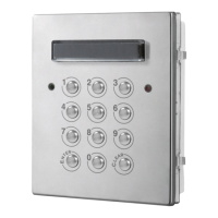
LOCK RELEASE BACK EMF PROTECTION
A varistor must be tted across the terminals on AC lock release
(Fig.1A)
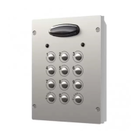
and a diode must be tted across the terminals on a DC
lock release
(Fig.1B) to suppress back EMF voltages. Connect the components to the lock releases as shown in gures.
VARISTOR (MOV)
12V AC
LOCK RELEASE
Fig.1A
1N4002
12V DC
LOCK RELEASE
Fig.1B
BUZZER BACK EMF
When using intercoms with buzzer call (Art.924/926, SMART1/2, 3101/2, 3001/2 and 3021/2) add one 0.1uF (100nF) capacitor be-
tween terminals 3 and 6 on the telephone.
BUILTIN RELAYS BACK EMF PROTECTION
The Art.4901 includes selectable back EMF protection on the relays. The jumpers marked MOV (one jumper for each relay) are used
to select the protection type. When using a fail secure lock with connections C & NO the jumper should be in the NO position. When
using a fail open lock with connections C & NC the jumper should be in the NC position and when using the codelock to trigger a gate
controller or another third party controller the jumper should be removed completely (this disables the protection on the relay).
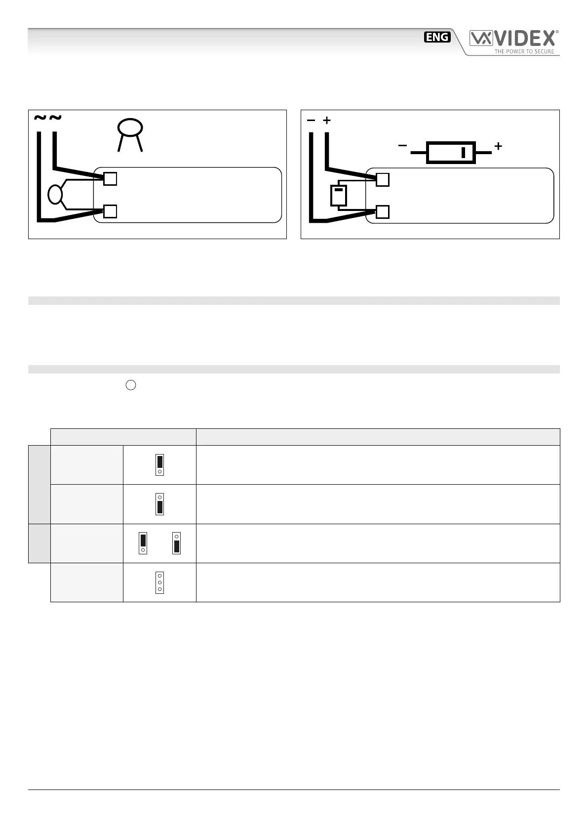
BACK LIGHT ADJUSTMENT JUMPER JPL
The jumper JPL (Fig.2,
D
) is used to adjust the brightness and determine the operation of the backlit buttons. There are four
brightness settings for the backlit buttons and two programming modes (mode 1 and 2) for the jumper.
The two modes that can be programmed change the functionality of the jumper JPL. The table below indicates the programming
mode, the position of the jumper and the operation of the backlit buttons.
Jumper Position Back light Operation
Mode 1
A
(default)
Back light on low brightness in standby. Full brightness when any buttons are pressed.
B
Back light OFF in standby. Full brightness when any buttons are pressed.
Mode 2
A or B
or
Back light on full brightness all of the time.
JPL removed in
either Mode
No back light, the back light is completely disabled.
Art.4901 Digital codelock module
 Loading...