10
Mit der Ösen-Biegezange (Art.-Nr. 4198) von
Viessmann können Sie auch die Fahrdrahtlängen
bzw. Mastabstände indviduell Ihrer Anlage ent-
sprechend festlegen. Der maximale Mastabstand
ist vom Gleisbogenradius R und der Seitenabwei-
chung des Fahrdrahtes S abhängig. Er kann nach
folgender Formel errechnet werden:
L max. = 4 x √ R x S
With the eye hook bending pliers (item-No. 4198)
from Viessmann you can adjust the length of the
catenary wires or the distance between the masts
to t your individual layout. The maximum distance
is depending on the radius of the track curve R and
the sideways deviation of catenary wire S. It can be
calculated with the following formula:
L max. = 4 x √ R x S
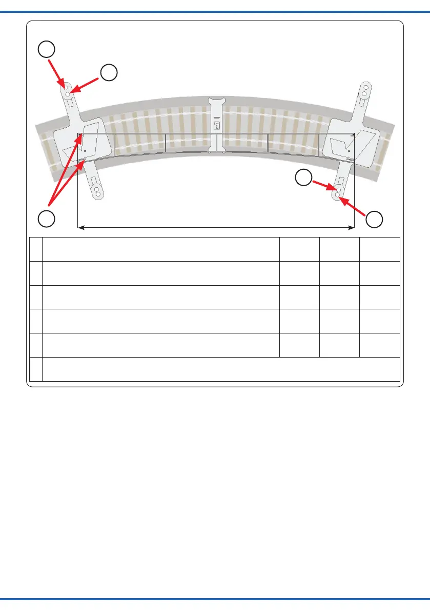
Fig. 12
Abb. 12
Verwendung der Mastpositionslehre
Use of the mast position gauge
Fahrdrahtlänge / Length of the contact wire
H0
4197
TT
4297
N
4397
1 Abstand zur Gleismitte für Quertragwerke
Distance to the middle of the tracks, for headspans
40 mm 29 mm 23 mm
2 Abstand zur Gleismitte für Abspannmasten mit Ausleger
Distance to the middle of the tracks, for tensioning masts with bracket
35,4 mm 26 mm 20 mm
3 Abstand zur Gleismitte für Streckenmasten
Distance to the middle of the tracks, for all standard masts
34 mm 25 mm 19 mm
4 Abstand zur Gleismitte für Turmmasten mit Ausleger
Distance to the middle of the tracks, for tower masts with beam
37,5 mm 27,5 mm 20,7 mm
5 Fahrdrahtaufnahmen
Running wire fastening
1
2
3
5
4