8
5. Betrieb
Der Decoder verfügt über zahlreiche Funktionali-
täten.
5.1 Eingänge
Es gibt jeweils zwei Schalteingänge, mit denen Sie
die Gruppe ein- und ausschalten können.
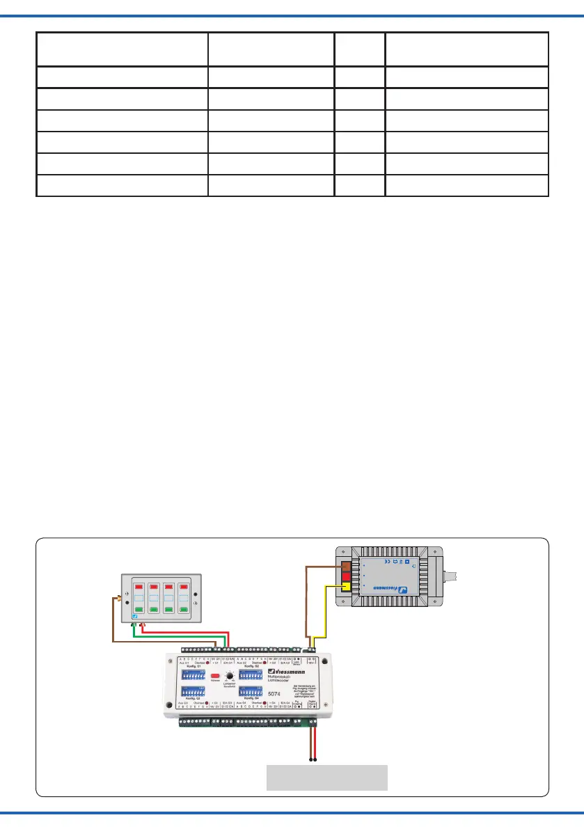
Sie können die Ausgänge über Taster aktivieren und
deaktivieren (Grundzustand; Abb. 3).
Um einen Betrieb mit Schalter zu realisieren stellen
Sie die CVs 46 – 49 dementsprechend ein.
Mit einem Schalter schalten Sie eine Verbindung
von der braunen Leitung (Abb. 3) auf E1 oder E2
ein oder aus, wenn Sie die CVs 46 – 49 (siehe CV-
Tabelle) dementsprechend eingestellt haben. Wenn
Sie die Verbindung aktivieren, aktivieren Sie damit
auch die Gruppe.
5. Operation
The decoder supports numerous functionalities.
5.1 Inputs
For each group there are two gate inputs by which
you can switch the group on and off.
You can activate and deactivate the outputs by
push-buttons (initial state; fig. 3).
In order to operate with a switch you have to set the
CVs 46 – 49 accordingly.
With a switch you switch a connection between
the brown wire (fig. 3) and E1 or E2 on and off if
you have configured CVs 46 – 49 accordingly (see
CV table). When you activate the connection, you
activate the whole group at the same time.
Sekundär
0-10-16 V~
16 V
Primär
230 V~
Gefertigt nach
VDE 0570
EN 61558
Lichttransformator
5200
Nur für trockene Räume
Primär 230 V 50 - 60 Hz
Sekundär max. 3,25 A52 VA
ta 25°CIP 40
10 V
0 V
z. B. / e. g. 5200
16 V~
Digitalzentrale
Digital command station
braun
brown
gelb
yellow
braun
brown
rot
red
Universal Tasten - Stellpult
5547
Viessmann
Fig. 3
Abb. 3
Decoderadresse (Gruppe)
Decoder address (group)
Schaltartikeladresse
Address
CV 9 =
MSB
CV 1 = LSB
1 1, 2, 3, 4 0 1
2 5, 6, 7, 8 0 2
.... .... .... ....
63 249, 250, 251, 252 0 63
64 253, 254, 255, 256 1 0
212 845, 846, 847, 848 3 20 (212/64 = 3, Rest x 64 = 20)