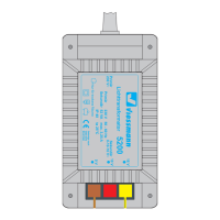
Sekundär
16 V ~
Primär
230 V ~
Gefertigt nach
VDE 0551
EN 60742
Lichttransformator
5200
Nur für trockene Räume
Primär 50/60 Hz230 V
Sekundär max. 3,25 A52 VA
ta 25°CIP 40
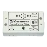
viessmann
Soundmodul
Synchron-
eingang
14-16V
~ / =
5556
intern / extern
Synchron-
ausgang
Universal Tasten - Stellpult
5547
Viessmann
gelb
braun
z. B. 5200
z. B. 5100
grün
5556
2 x blau
z. B. 5547
Anschluss Synchronausgang:
Maximale Kontaktbelastbarkeit 2 A!
2 x blau
grüne Marker
rote Marker
/ brown
e. g. 5200
yellow
e. g. 5100
green
/ blue
e. g. 5547
Connector synchron output:
Maximum load of “Synchronausgang” 2 A!
2 x blue
red marker
green marker
Fig. 1
Abb. 1
Soundmodul Bahnübergang
5556
Zum Betrieb des Soundmoduls mit den Viessmann
Bahnschranken 5100, 5104, 5700 oder 5900 beach-
ten Sie bitte die besonderen Hinweise zur Verkabe-
lung in dieser Zusatzanleitung.
Anschluss
Die Betriebsspannung des Soundmoduls
beträgt 14 – 16 V = / ~.
Alle Anschluss- und Montagearbeiten dür-
fen nur bei abgeschalteter Betriebsspannung
durchgeführt werden!
Verwenden Sie nur nach VDE / EN-gefertigte
Modellbahntransformatoren!
Schließen Sie das Soundmodul und die Schranken
gemäß Abbildung 1 (Taster) oder 2 (Schalter) an.
Sound module “level crossing”
5556
Please observe the following instructions regard-
ing the cabling to use this sound module in com-
bination with the Viessmann barriers 5100, 5104,
5700 or 5900.
Connection
The operating voltage of the sound module is
14 – 16 V AC / DC.
All mounting and connection works must
only be executed after the power supply is
cut off.
Only use model railway transformers build
according to VDE / EN!
Connect the sound module and the drive units of
the barriers accordingly g. 1 (push button) or 2
(switches) to the power supply.
Zusatzanleitung 5556
Supplementary Manual 5556