12
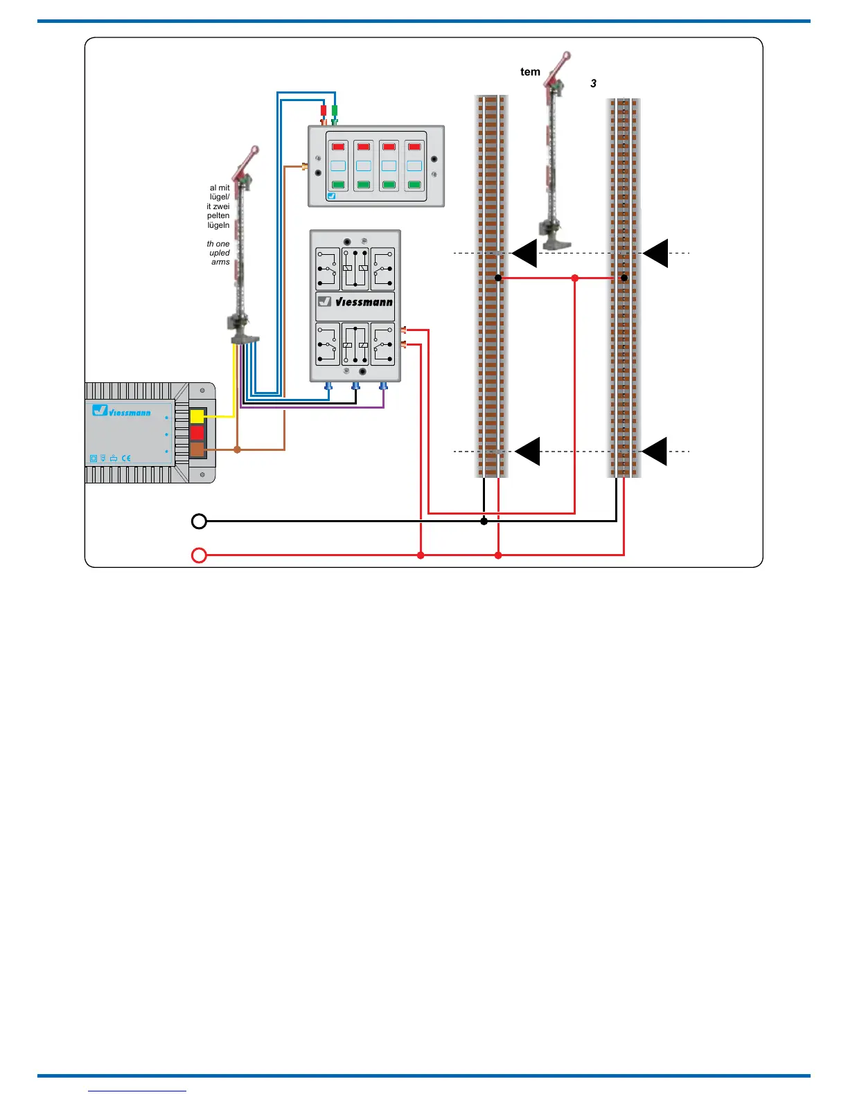
- Schaltausgang mit blauer Leitung: Bei Ansteuerung
von Hp1/Hp2 (über grün markierte Leitung oder
Schaltbefehl grün) liegt hier für ca. 0,25 Sekun-
den nach Ende der Signalbewegung eine posi-
tive Spannung von ca. 16 – 20 V an.
- Schaltausgang mit lilafarbener Leitung: Bei
Ansteuerung von Hp0 (über rot markierte Lei-
tung oder Schaltbefehl rot) liegt hier für ca.
0,25 Sekunden eine positive Spannung von ca.
16 – 20 V an.
- Die schwarze Leitung ist die gemeinsame
Masse.
Bitte beachten Sie, dass für Signale mit zwei unge-
koppelten Flügeln eine andere Betriebsart in CV 38
ausgewählt werden kann. Dadurch kann ein Schal-
4.10 Weitere Funktionen
der Schaltausgänge
Außer dem schon beschriebenen Schaltimpuls
können die Ausgänge auch auf Dauerkontakt
geschaltet werden. Dabei wird der jeweilige Aus-
gang am Ende der Bewegung aktiviert.
Weitere Möglichkeiten entnehmen Sie bitte der
CV-Tabelle unter CV 38.
positive voltage of ca. 16 V to 20 V present for
about 0,25 seconds after the signal movement.
- Output with the purple wire: When activat-
ing Hp0 (via the wire with the red marking or
switching command with red button) there will
be a positive voltage of ca. 16 V to 20 V pre-
sent for about 0,25 seconds after the signal
movement.
- The black wire is the common ground.
Please note that you may select a dierent operat-
ing mode for signals with two uncoupled sema-
phore arms in CV 38. This facilitates the option of
linking an output with the Hp2 aspect.
4.10 Other functions of the switching
outputs
Besides the switching pulse already described, the
outputs can also be set to continuous mode with
various commands (refer to CV 38). The outputs
can be digitally switched as continous outputs.
You will nd more options under CV 38 in the CV-
table.
 Loading...