6
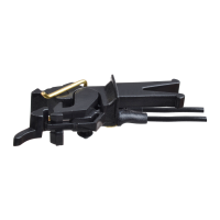
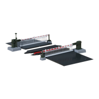
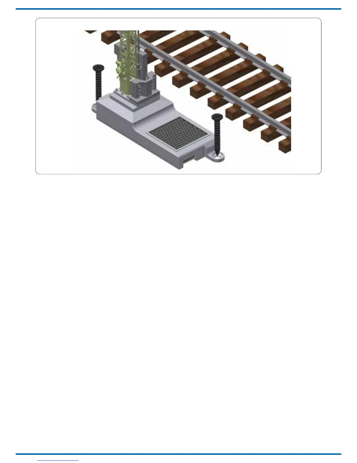
Fig. 3Abb. 3
4.2 Analoger Betrieb
Im analogen Betrieb schalten Sie das Signal mit
geeigneten Tastenstellpulten, z. B. Art.-Nr. 5546
(für Signale mit zwei ungekoppelten Flügeln) und
Art.-Nr. 5547 (für Signale mit einem Flügel und
Signale mit zwei gekoppelten Flügeln).
Schließen Sie das Signal und das Tastenstellpult
wie in Abb. 4 bzw. Abb. 5 gezeigt an. Verwenden Sie
einen geeigneten Transformator (z. B. Art.-Nr. 5200).
4.3 Digitalbetrieb
Dieser Decoder lässt sich als Schaltartikel ansteuern.
Er bietet aber auch den Komfort, auf einer Lokad-
resse angesteuert werden zu können. Dies kommt
den Modellbahnern entgegen, deren Zentrale kei-
-
licht, siehe Kapitel 5.6 (Digitalbetrieb auf einer
(Expertenmodus).
Im digitalen Betrieb schalten Sie das Signal über
eine Digitalzentrale. Legen Sie als erstes eine
Digitaldresse fest. Lesen Sie dazu die beiden fol-
genden Kapitel und beachten Sie Abb. 6.
Nach Festlegung der Digitaladresse schließen Sie
das Signal an (Abb. 7).
4.4 Einrichtung mit DCC-Zentralen
Zur digitalen Steuerung des Signals müssen Sie
diesem zunächst eine Digitaladresse zuweisen.
Zur Steuerung im DCC-System gehen Sie wie
folgt vor:
1. Schalten Sie das Digitalsystem aus, z. B. Not-Aus.
Es darf keine Spannung mehr am Gleis anliegen.
4.2 Operation in analogue mode
In case that you use the Viessmann signal on
analogue layouts, use a push button panel item-
No. 5546 (for signals with two uncoupled arms)
or item-No. 5547 (for signals with one semaphore
arm and signals with two coupled arms).
Connect the signal and the push button panel as
shown in g. 4 and 5. Use a suitable transformer
(e. g. item-No. 5200).
4.3 Operation in digital mode
This decoder can be controlled as an switch-
ing decoder. However, it also oers the option to
be controlled with a locomotive address. This is
particularly useful for modellers who do not have
a command station with easy access to acces-
sories; refer to chapter 5.6 (digital operation of a
locomotive address). You will nd more details in
chapter 8 (Expert mode).
In the digital mode of operation, you use a digital
command station to control the signal. Please
read the following two chapters to learn how to set
a digital address and note g. 6.
Connect the signal to your digital layout as shown
in g. 7.
4.4 Conguration with DCC command stations
To use the signal in a digital environment, at rst
you have to assign a digital address. To control
the signal with a DCC-system, observe the
following instructions:
1. Switch o the digital system (e. g. emergency
o). There must not be any power at the rails.
 Loading...