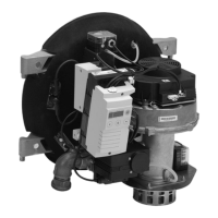
26
A
Burner control unit MPA5113
B
Vitotronic control unit
C
Fan motor with PWM control and
feedback
D
Flame monitoring by means of ioni-
sation current
E
Display unit with reset function
F
Air pressure switch
G
Gas pressure switch
H
Ignition unit
K
Solenoid valve stage 2 (BV 2)
L
Solenoid valve stage 1 (BV 1)
M
Servomotor for rotary damper
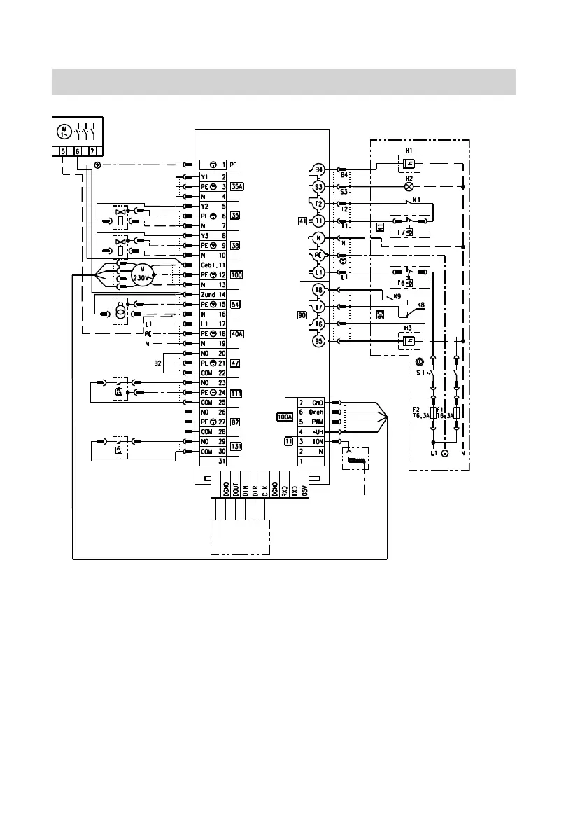
B2 Safety chain jumper
F1 MCB/fuse
F2 MCB/fuse
F6 High limit safety cut-out
F7 Temperature controller
H1 Hours run meter, modulation
H2 Fault message
H3 Hours run meter, modulation
S1 ON/OFF switch
Connection diagram
Connection diagram
5782 991 GB